Lever cylinder for fixture

A lever cylinder and fixture technology, applied in the field of fixture cylinders, can solve the problems of straight cylinders not being able to output greater clamping force, multiple spaces, and iron filings scalding the air pipe, etc.

Inactive Publication Date: 2008-11-12
NINGBO FENGZHOU MACHINERY
View PDF0 Cites 20 Cited by
  • Summary
  • Abstract
  • Description
  • Claims
  • Application Information

AI Technical Summary

Problems solved by technology

[0004] 1. The existing straight cylinder cannot output greater clamping force on the basis of cylinder diameter and space constraints
[0005] 2. The existing straight-travel cylinders all enter the oil from the side of the cylinder body, and the cylinder body is usually screwed and fixed on the base plate, so the straight-travel cylinder used as a fixture will form too many inlet, outlet or oil pipes on the upper part of the base plate. The iron filings generated during the processing of the workpiece will gather between various pipes, and the iron fi

Method used


Image

  • Lever cylinder for fixture
  • Lever cylinder for fixture
  • Lever cylinder for fixture

Examples


Example Embodiment

[0021] The present invention will be further described in detail below with reference to the embodiments of the drawings.

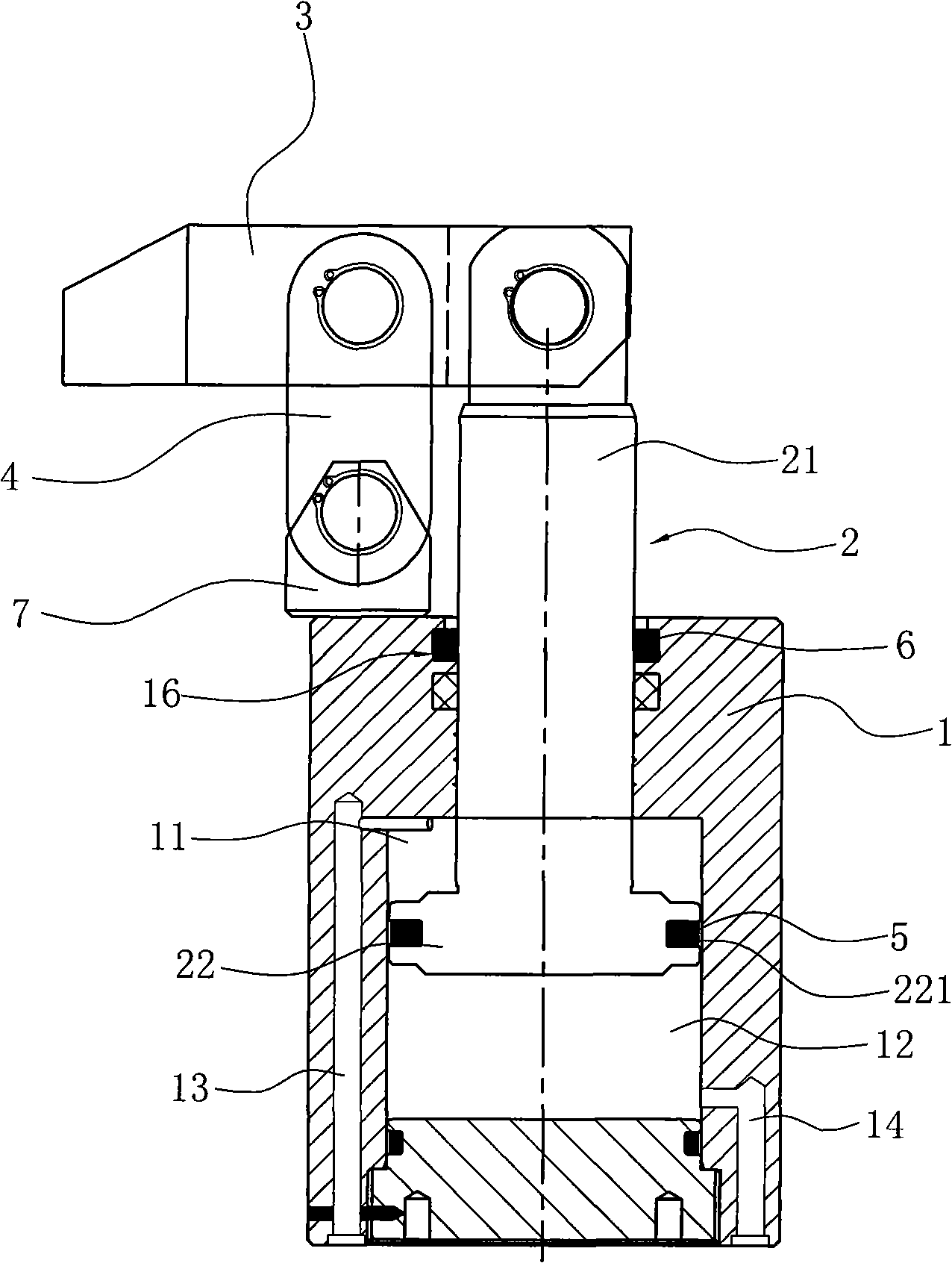
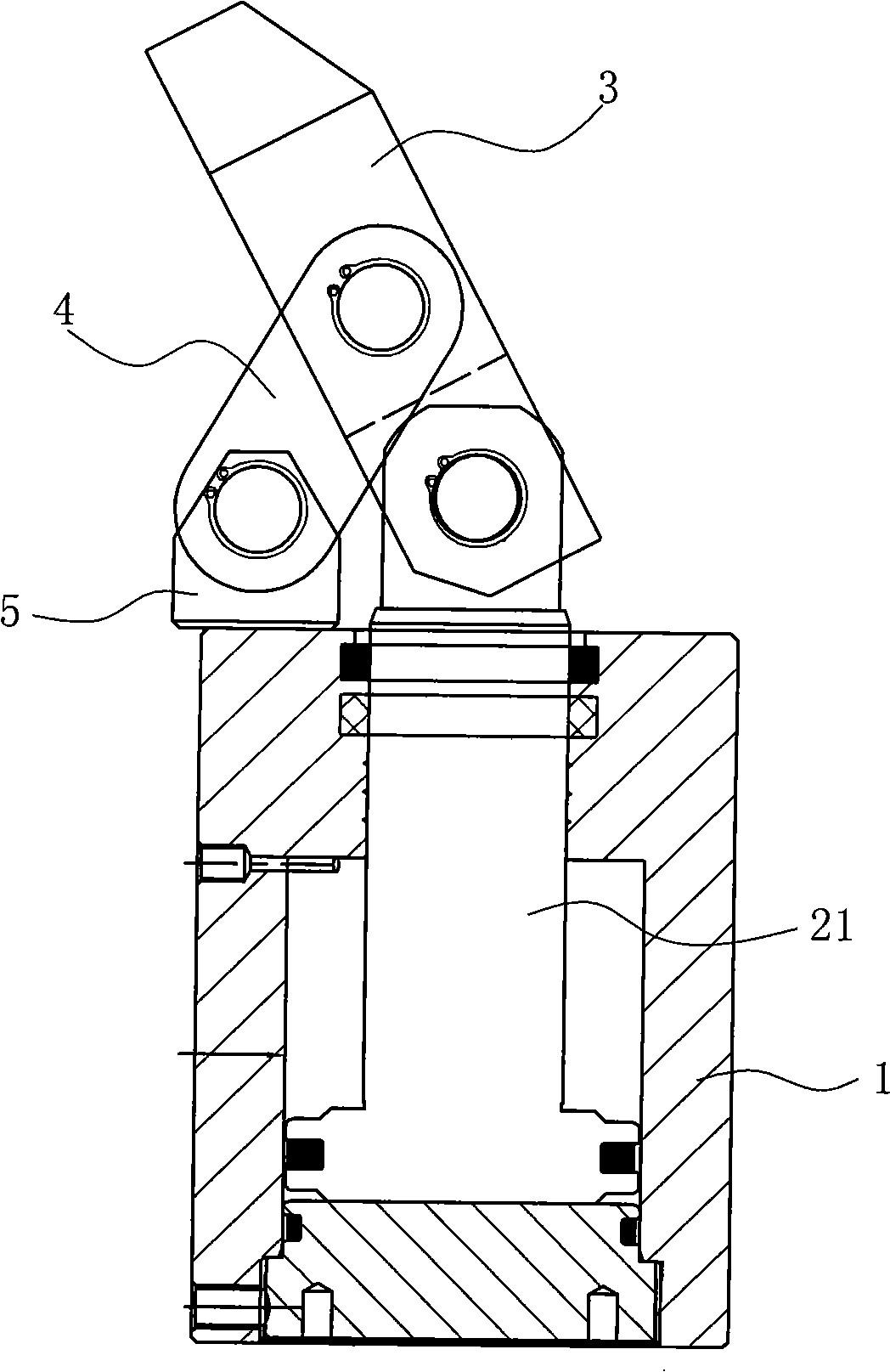
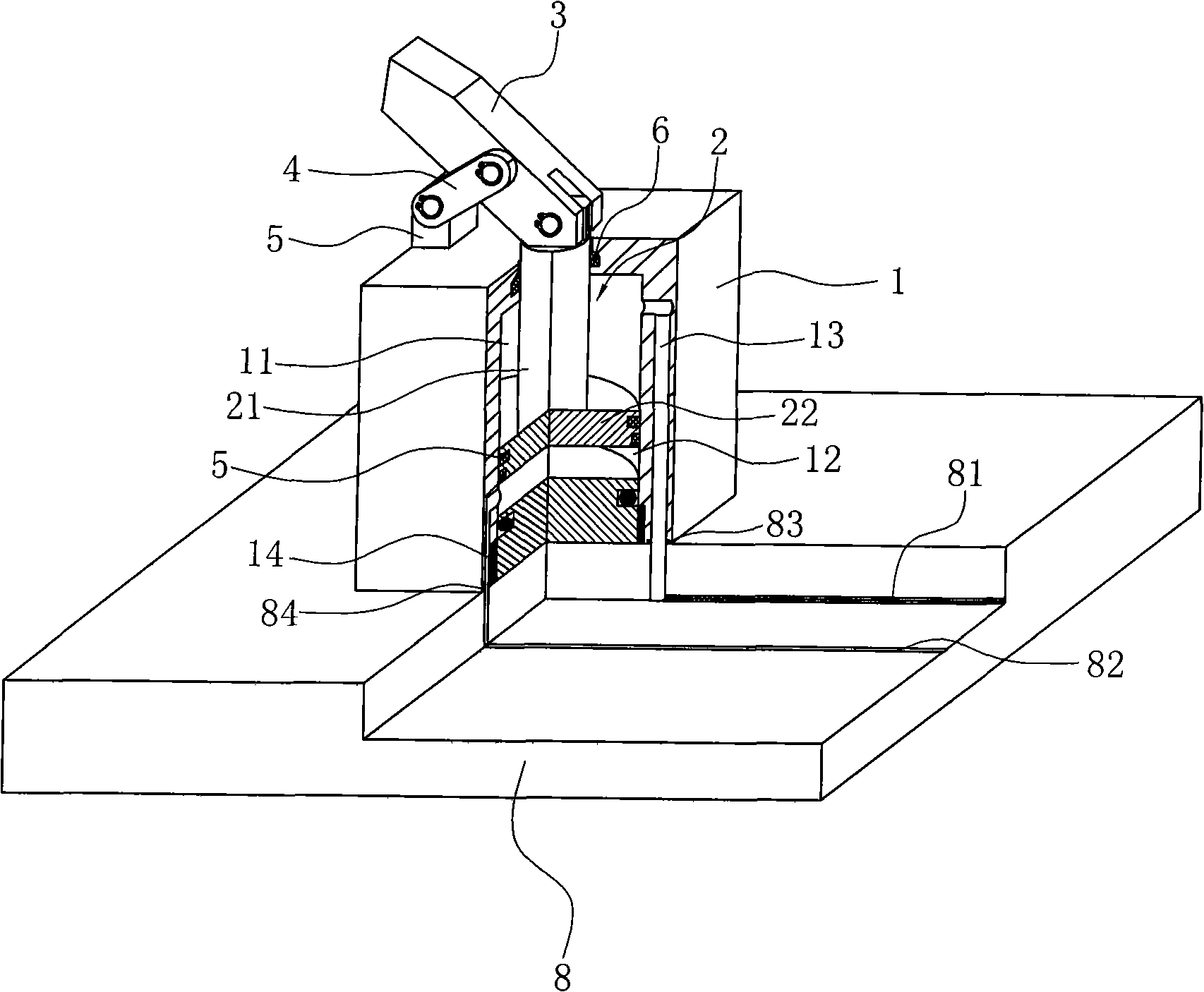
[0022] Such as figure 1 , 2 , 3 shows the first embodiment of the present invention.

[0023] A lever cylinder for clamps includes a cylinder block 1, a piston rod 2 installed in the cylinder block 1, a rod portion 21 of the piston rod 2 extends out of the cylinder block 1, and a piston portion 22 of the piston rod 2 and the inner wall of the cylinder block 1 A first sealing ring 5 is provided for sealing. The first sealing ring 5 is mounted on the annular groove 221 on the outer peripheral surface of the piston 22. A second sealing ring 6 is also provided between the rod 21 of the piston rod 2 and the inner wall of the cylinder 1 to seal. The second sealing ring 6 is installed on the annular groove 16 on the inner peripheral surface of the axial through hole of the cylinder 1 to fully ensure that the piston rod 21 is in a liquid-tight fit with the inner wal...


PUM


Abstract

The invention discloses a lever cylinder used for fixtures, which comprises a cylinder body (1) and a piston rod (2) arranged in the cylinder body (1), wherein, the upper end of the piston rod (2) extends out of the cylinder body (1) and the piston rod (2) is matched with the inner wall of the cylinder body (1) by liquid seal and divides the inner space of the cylinder body (1) into two seal cavities, an upper seal cavity (11) and a lower seal cavity (12). The cylinder body (1) is provided with a first channel (13) communicated with the upper seal cavity (11) and a second channel (14) communicated with the lower seal cavity (12). The lever cylinder of the invention is characterized in that the upper part of the piston rod (2), extending out of the cylinder body (1), is articulated with a pressure plate (3) and a pulling plate (4), the upper end of pulling plate (4) is articulated with the middle part of the pressure plate (3) while the lower end thereof is articulated with the upper part of the cylinder body (1). The up-down movement of the piston rod drives one end of the pressure plate to move down, and the pressing force of the outer end of the pressure plate is more than the upward pushing force of the piston rod according to the lever principle, thus realizing the output of more clamping force on the basis of limitations of cylinder diameter and space.

Description

technical field [0001] The invention relates to a cylinder for a clamp, in particular to a lever cylinder for a clamp. Background technique [0002] With the vigorous development of the machining center industry, it has led to the rise of the domestic professional fixture industry, and the rapid development of the domestic automobile, aerospace and other industries requires more and more complexity and precision of batch spare parts. The difficulty and speed of industrial parts processing require the rapid development of the domestic fixture industry. [0003] The existing hydraulic cylinders or air cylinders or air hydraulic cylinders for fixtures are generally straight cylinders. As an improvement of the straight cylinders, there is also a corner cylinder. The advantage of the corner cylinder is that the corner guide rod can rotate 180 degrees during the work process. ° angle, to avoid the workpiece. But there is following defect in existing fixture cylinder: [0004] 1...

Claims


Application Information

Patent Timeline
IPC IPC(8): F15B15/06F15B15/14B23Q3/06
Inventor 孙秀云苏利艳
Owner NINGBO FENGZHOU MACHINERY
Why Eureka
Try Eureka