Positioning clamping device for workpiece

A positioning clamping and workpiece positioning technology, which is applied in the field of positioning clamping devices and workpiece positioning clamping devices, can solve problems such as clamping deviation, quality defects, and unclamped workpieces, and achieve enlarged retractable radius, simple structure, and clamping strong effect

Inactive Publication Date: 2012-12-05
鹿丙稳
View PDF0 Cites 22 Cited by
  • Summary
  • Abstract
  • Description
  • Claims
  • Application Information

AI Technical Summary

Problems solved by technology

[0003] Among the above-mentioned positioning methods, although the method of using a general-purpose chuck has the characteristics of high precision, the investment cost of the chuck is generally high, and there is generally no corresponding large-sized chuck for large-diameter ring workpieces; The method of bolt direct positioning and manual correction is relatively simple, but it has high labor intensity and low productivity. At the same time, due to human negligence, it often happens that the workpiece is not clamped and the clamping

Method used


Image

  • Positioning clamping device for workpiece

Examples


Example Embodiment

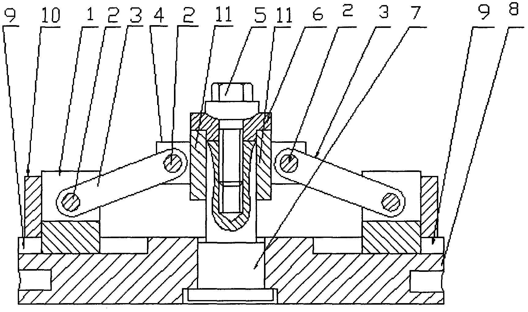
[0011] On the upper plane of the base 8, an appropriate number of guide grooves 9 are made along the center radius, and a stepped through hole is made at the center of the base 8, and the center axis of the hole is kept perpendicular to the upper and lower planes of the base 8. Insert the mandrel 7 and the slider 1 into the center hole of the base 8 and the guide groove 9 respectively. When assembling, make sure that the connecting sleeve 4 and the bushing 6 are installed on the mandrel 7 and in the middle of the mandrel 7 at the same time. Screw the afterburner bolt 5 into the threaded hole, and use the pin 2 to hinge the slider 1 and the connecting sleeve 4 together. The working principle is: install the mandrel 7 in the center of the base 8. The mandrel 7 and the upper and lower planes of the base 8 are kept perpendicular to each other. On the upper plane of the base 8, a number of rail grooves distributed from the center of the base 8 to the surrounding are formed. 9. The s...


PUM


Abstract

The invention relates to a positioning clamping device for a workpiece. A spindle is mounted at the center of a base; the spindle is kept vertical to upper and lower planes of the base; a plurality of guide rail slots scattering from the center of the base to the periphery are formed on the upper plane of the base; slide blocks are mounted in the guide rail slots; connecting rods and a connecting sleeve are mounted on the spindle; corresponding fork-shaped lugs are formed on the periphery of an outer circle of the connecting sleeve; one ends of the connecting rods are hinged with the corresponding slide blocks through pin shafts; and the other ends of the connecting rods are hinged with each other through the pin shafts and the fork-shaped lugs on the connecting sleeve. The end parts of the connecting rods are hinged with the slide blocks through the pin shafts, the slide blocks only can move in the fixed guide rail slots, a threaded hole is formed in the middle of the spindle, a bush is mounted on the connecting sleeve, a thrusting bolt is screwed into the threaded hole in the middle of the spindle from a middle hole of the bush, and a function of pressing the connecting sleeve is achieved, so that the purpose of supporting an inner circle of the workpiece through the slide blocks is achieved.

Description

technical field [0001] The invention relates to a positioning and clamping device, in particular to a workpiece positioning and clamping device. The utility model belongs to the technical field of machine tools and lathes. Background technique [0002] At present, in the metal cutting process, in order to cut the outer circle of the annular workpiece, the annular workpiece to be processed must be positioned on the machine tool used in advance. Among all the current positioning methods, there are mainly: one is to use the method of universal chuck for positioning; the other is to use the method of bolt positioning and manual correction for positioning; the third is to use the method of elastic chuck for positioning; the fourth is to use the method of mandrel position. [0003] Among the above-mentioned positioning methods, although the method of using a general-purpose chuck has the characteristics of high precision, the investment cost of the chuck is generally high, and t...

Claims


Application Information

Patent Timeline
IPC IPC(8): B23Q3/06
Inventor 鹿丙稳
Owner 鹿丙稳
Why Eureka
Try Eureka