Electronic parking brake system and control method thereof

A technology of electronic parking brake and brake motor, which is applied in the direction of brakes, brake transmission devices, vehicle components, etc., can solve problems such as safety accidents, engine flameout, and vehicle rollback, so as to avoid vehicle slippage and control methods Reliable, low-cost results

Active Publication Date: 2010-09-08
CHERY AUTOMOBILE CO LTD
View PDF4 Cites 22 Cited by
  • Summary
  • Abstract
  • Description
  • Claims
  • Application Information

AI Technical Summary

Problems solved by technology

At present, an electronic control unit (patent application number: CN200810121737.3) of a vehicle electronic parking brake system is disclosed. The electronic control unit includes a microcontroller, a power conversion module, a reset circuit module, a clock circuit module, and an input channel module. , The brake motor drive module, the microcontroller receives the signal transmitted by the input channel module, after a certain control strategy calculation, the control signal is generated and sent to the brake motor drive module, and the brake motor drive module performs forward and reverse rotation of the motor While controlling, it provides current feedback to the microcontroller, thus forming a closed-loop control system to realize the function of electronic parking brake, but its disadvantage is that the parking function is only implemented when the vehicle speed is equal to zero, and when the car is parked on the ramp When preparing to start, if the driver is inexperienced and does not cooperate properly, it is easy to cause the engine to stall and the vehicle to "slip", and even cause a safety accident.

Method used


Image

  • Electronic parking brake system and control method thereof
  • Electronic parking brake system and control method thereof

Examples


Embodiment 1

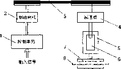
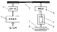
[0019] Such as figure 1 As shown, the electronic parking brake system of this embodiment includes a control unit 1 and a brake motor 2 controlled by the control unit 1, and the input signal of the control unit 1 includes a throttle opening sensor, a clutch sensor, an engine speed sensor , the current sensor of the brake motor, the vehicle speed sensor, the handbrake switch, the signal of the ramp start switch, the brake motor 2 drives the reducer 4 through the belt 3, drives the worm gear 5 to rotate after the reducer 4 decelerates, and the turbine The worm 5 is covered with a screw mandrel 6, and the end of the screw mandrel 6 is fixed with a friction plate 7, and the friction plate 7 is close to the brake disc 8 of the automobile braking system.

[0020] The brake motor 2 is a permanent magnet DC motor.

[0021] The above-mentioned control method of the electronic parking brake system, the method includes the following steps:

[0022] A: After the control unit 1 receives t...


PUM


Abstract

The invention aims to provide an electronic parking brake system which can be controlled simply and reliably and has a control method of an assistant hill starting function. The electronic parking brake system comprises a control unit and a brake motor which is controlled by the control unit and the signal input end of the control unit is connected with a throttle opening sensor, a clutch sensor, an engine rotating speed sensor, a current sensor of the brake motor, a hand brake switch and a hill start switch; the brake motor drives a turbine worm to rotate through a driving mechanism; the turbine worm is sleeved with a screw rod, and the end part of the screw rod is fixed with a friction plate. The electronic parking brake system has the advantages of greatly reducing the operational difficulty of a driver and improving the driving and operating comfort and convenience, along with low cost, simple structure, reliable control method, basic function of the traditional hand brake and assistant hill start function.

Description

technical field [0001] The invention belongs to the field of automobile braking, in particular to an automobile braking system. Background technique [0002] With the continuous advancement of automobile technology, more and more automobiles have gradually changed from traditional mechanical control to electronic control. The electronic parking brake system uses electric energy to realize the functions of the traditional parking brake system. At present, an electronic control unit (patent application number: CN200810121737.3) of a vehicle electronic parking brake system is disclosed. The electronic control unit includes a microcontroller, a power conversion module, a reset circuit module, a clock circuit module, and an input channel module. , The brake motor drive module, the microcontroller receives the signal transmitted by the input channel module, after a certain control strategy calculation, the control signal is generated and sent to the brake motor drive module, and t...

Claims


Application Information

Patent Timeline
Patent Type & Authority Applications(China)
IPC IPC(8): B60T13/74
Inventor 杜金枝
Owner CHERY AUTOMOBILE CO LTD
Why Eureka
Try Eureka