
System for fastening a rail

Active Publication Date: 2009-04-02
VOSSLOH WERKE GMBH
View PDF8 Cites 20 Cited by
  • Summary
  • Abstract
  • Description
  • Claims
  • Application Information

AI Technical Summary

Benefits of technology

[0008]In general, in one aspect, the invention provides a fastening system allowing, fastening of rails that satisfies modern requirements wit

Problems solved by technology

However, they do not meet the requi

Method used


Image

  • System for fastening a rail
  • System for fastening a rail
  • System for fastening a rail

Examples


Example

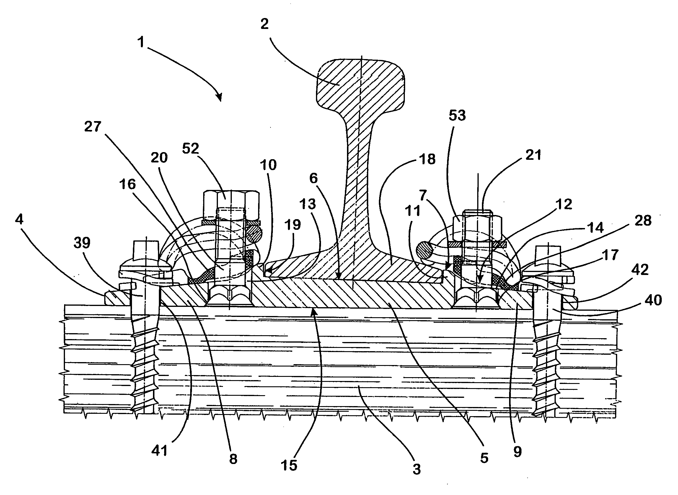
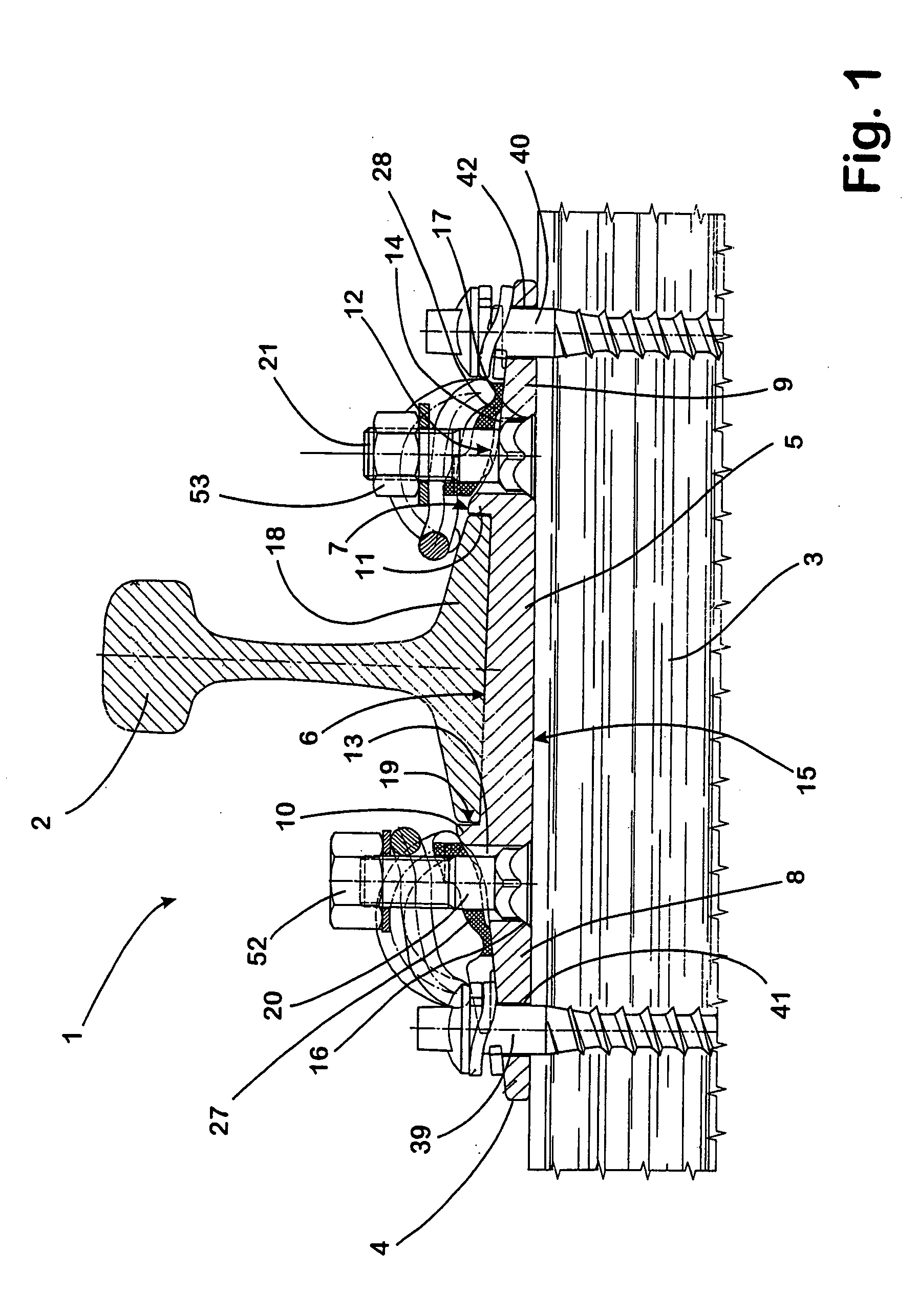
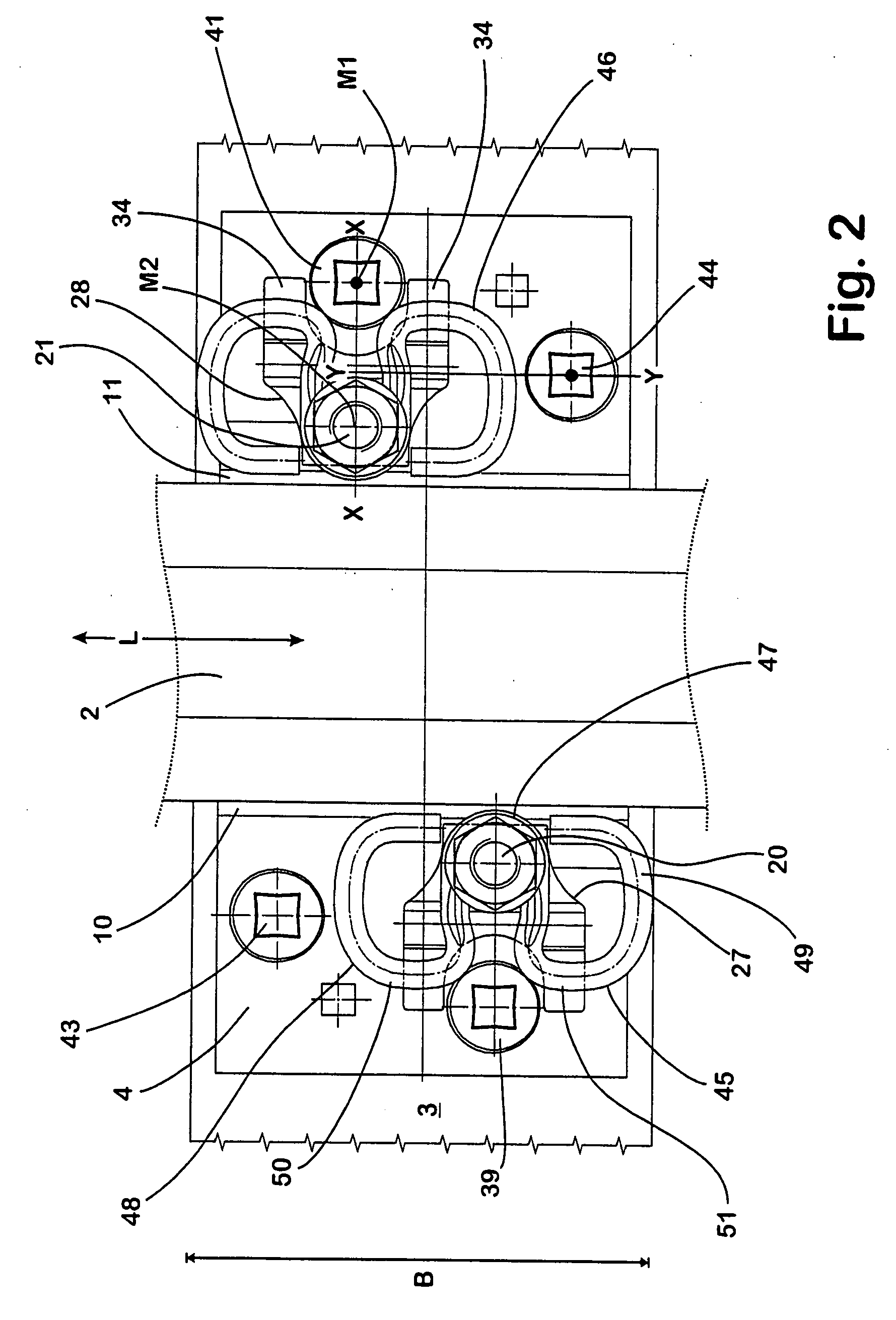
[0034]The system 1 for fastening a rail 2 on a wooden sleeper 3 comprises a conventionally shaped base plate 4 into which a central portion 5 extending over the entire width B of the base plate 4 is molded.

[0035]The bottom 6 of the central portion 5 is lowered relative to the adjoining free surface 7 of the side portions 8, 9 of the base plate 4 adjoining the central portion 5 on both sides, so that the central portion 5 is laterally delimited by rib shoulders 10, 11 likewise extending over the entire width B of the base plate 4 in the longitudinal direction L of the rail 2.

[0036]The rib shoulders 10, 11 pass in a groove-like transition 12 into the region of the side portions 10, 11 adjoining them on the side remote from the central portion 5. The transition 12 has in this case no defined shape and can differ from base plate to base plate. A respective first opening 13, 14, which is arranged in the close vicinity of the respective rib shoulder 10, 11, is molded into the side portion...


PUM


Abstract

A system for fastening a rail on a substrate includes a base plate, molded into which is a central portion, the width of which is adapted to the width of the rail foot of the rail to be fastened, with at least one fastening element for connecting the base plate to the substrate. The at least one tensioning element is provided for holding down the rail on the base plate. The system provides a fastening system allowing fastening of rails that satisfies modern requirements with the additional benefit of low production costs and simple assembly, while maintaining the basic configuration of the base plate provided and using simple means.

Description

CROSS-REFERENCE TO RELATED APPLICATIONS[0001]This application claims the benefit of and priority to German Patent Application No. DE 10 2007 045 466.1-25, filed on Sep. 21, 2007, which is owned by the assignee of the instant application. The disclosure of this application is incorporated herein by reference in its entirety.FIELD OF THE INVENTION[0002]The invention relates to a system for fastening a rail on a substrate, with a base plate, molded into which is a depressed central portion, the width of which is adapted to the width of the rail foot of the rail to be fastened, with at least one fastening element for connecting the base plate to the substrate and with at least one tensioning element provided for holding down the rail on the base plate.BACKGROUND[0003]Systems of this type are used in particular to fasten rails on a wooden sleeper in a simple manner. The purpose of the base plate, which is generally made of a steel as a hot-rolled or forged product, is in this case to tra...

Claims


Application Information

Patent Timeline
IPC IPC(8): E01B9/02
CPCE01B9/483
Inventor BOSTERLING, WINFRIEDSTEIDL, MICHAEL
Owner VOSSLOH WERKE GMBH
Learn More