Top bond pad for transducing head interconnect

a top bond pad and transducer head technology, applied in the direction of maintaining the alignment of the head carrier, recording information storage, instruments, etc., can solve the problems of increasing the slider and the size of the bond pad, reducing the space available along the side or edge of the slider for large numbers of electrically isolated bond pads, and reducing the reliability of conventional methods and equipment used for gold ball bonding

Inactive Publication Date: 2011-04-19
SEAGATE TECH LLC
View PDF28 Cites 29 Cited by
  • Summary
  • Abstract
  • Description
  • Claims
  • Application Information

AI Technical Summary

Problems solved by technology

Decreasing slider and bond pad sizes present numerous difficulties.
For example, conventional methods and equipment used for gold ball bonding are no longer reliable for smaller sliders wit

Method used


Image

  • Top bond pad for transducing head interconnect
  • Top bond pad for transducing head interconnect
  • Top bond pad for transducing head interconnect

Examples


Embodiment Construction

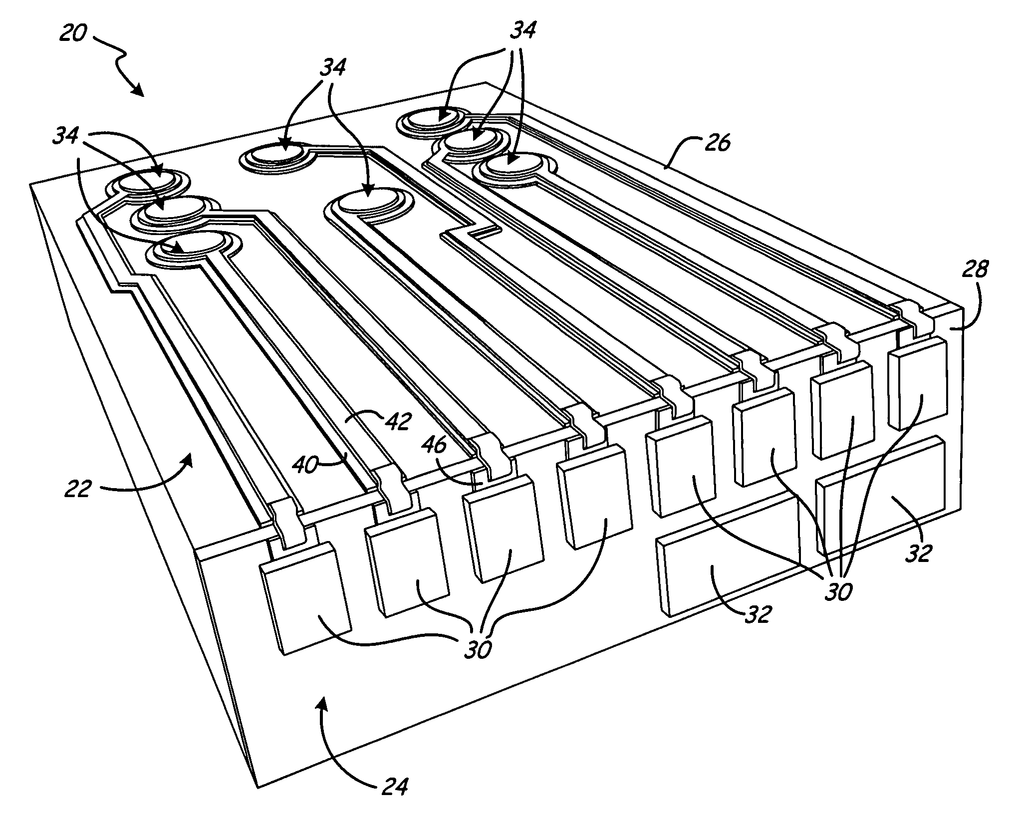
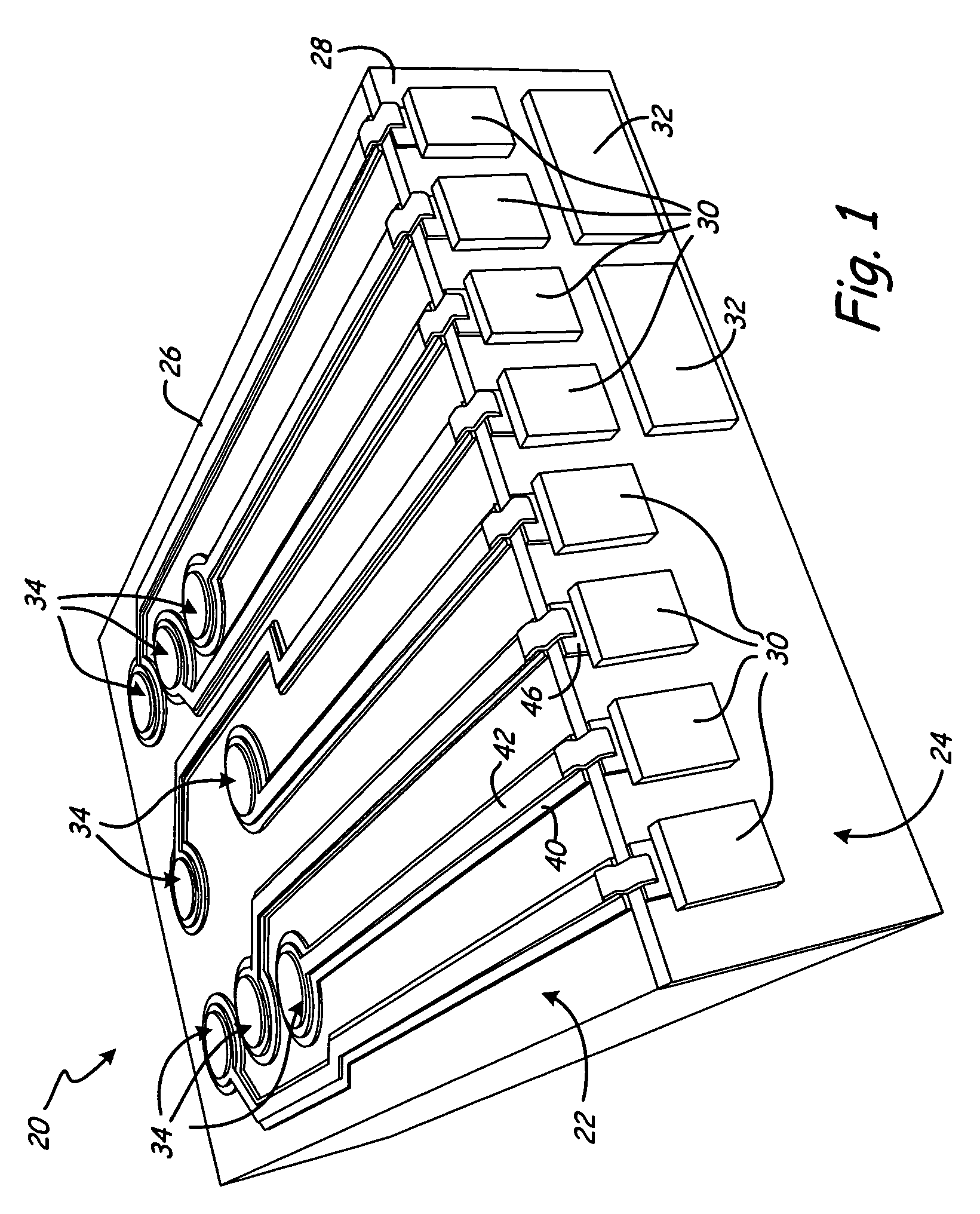
[0020]FIG. 1 is a perspective view of a slider assembly 20, showing a back side 22 (synonymously called the “top”) and a trailing edge 24 of the slider assembly 20. The slider assembly 20 includes a slider body 26 portion and an overcoat portion 28 that is located at the trailing edge 24. The overcoat portion 28 can include a number of individual layers that are not shown for simplicity. As shown in FIG. 1, a plurality of conventional trailing edge bond pads 30 and conventional lapping pads 32 are located at the trailing edge 24 of the slider assembly 20. A plurality of interconnect structures 34 are provided that extend along the back side 22 of the slider assembly 20. In the illustrated example, eight interconnect structures 34 are provided, and each interconnect structure 34 is electrically connected with a corresponding bond pad 30.

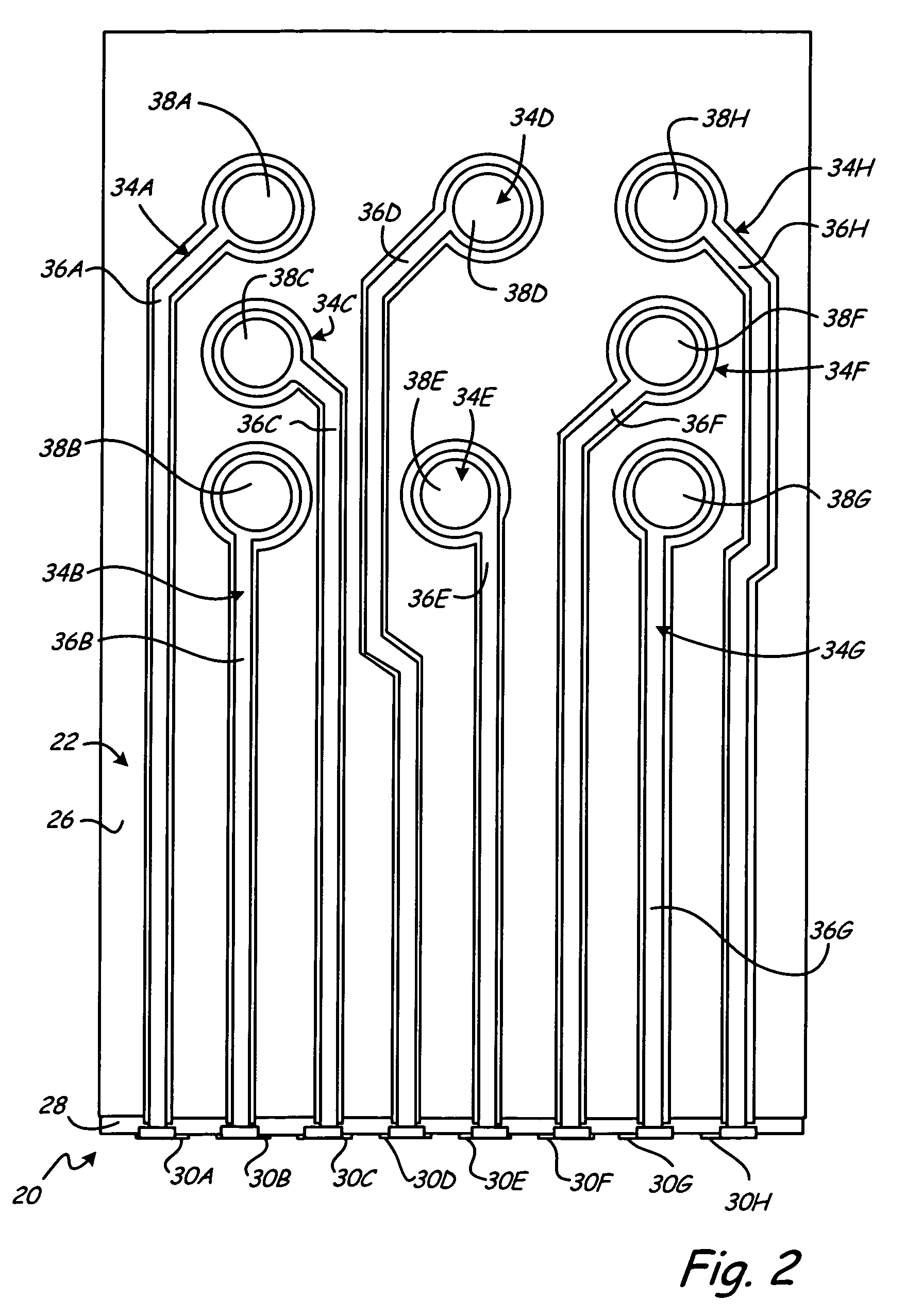
[0021]FIG. 2 is a top view of the slider assembly 20. As shown in FIG. 2, eight interconnect structures 34A-34H extend along the back side 22 of the ...


PUM


Abstract

A slider according to the present invention includes a slider body, a plurality of insulators, and conductive traces. The slider body has a first side and edges defined substantially perpendicular to the first side. The plurality of insulators are each adjacent to the first side of the slider body. The conductive traces are adjacent to each of the plurality of insulators and opposite the slider body.

Description

BACKGROUND OF THE INVENTION[0001]The present invention relates to electrical interconnection structures, and more particularly to interconnect trace and bond pad structures for use in conjunction with slider assemblies carrying transducing heads.[0002]Hard disc drives (HDDs) typically comprise one or more discs, each disc having concentric data tracks for storing data. Where multiple discs are used, a stack is formed of co-axial discs having generally the same diameter. A transducing head carried by a slider is used to read from and write to a data track on a disc. The slider is carried by a head arm assembly (HAA) that includes an actuator arm and a suspension assembly, which can include a separate gimbal structure or can integrally form a gimbal. As the disc is spun, the slider glides above the surface of the disc on a small cushion of air. The actuator arm movably positions the slider with respect to the disc. Electrical connections extend along the suspension to electrically con...

Claims


Application Information

Patent Timeline
IPC IPC(8): G11B5/60
CPCG11B5/4853G11B5/102
Inventor ZHU, JIANXINSLUZEWSKI, DAVID A.STOVER, LANCE E.HOEHN, JOEL W.SCHULZ, KEVIN J.
Owner SEAGATE TECH LLC
Why Eureka
Try Eureka