Hydrostatic testing tool and methods of use

a technology of hydrostatic testing and testing methods, applied in the direction of fluid tightness measurement, instruments, specific gravity measurement, etc., can solve the problems of limiting the rate of test production, requiring complex automatic equipment to do threading and unthreading, and requiring high labor intensity, so as to improve the seal, improve the reliability, and improve the effect of sealing

Active Publication Date: 2011-05-03
AIRMO INC
View PDF7 Cites 12 Cited by
  • Summary
  • Abstract
  • Description
  • Claims
  • Application Information

AI Technical Summary

Benefits of technology

[0011]It is an object of the present invention to provide a hydrostatic testing tool that may be quickly secured and unsecured to a threaded aperture of a test article, such as a container, hose or the like. It is another object of the present invention to provide a hydrostatic testing tool that is durable, provides a reliable seal and cannot become dislodged from the threaded aperture during testing.
[0025]The testing tool and methods of the present invention are also much safer and more reliable than the known expandable rubber plug method that involves inserting a rubber plug into the threaded aperture of the container and to then mechanically expanding the plug to sealably engage the threaded aperture. This known rubber plug method, when used at high pressures, has been unreliable and has created safety problems in that as the rubber plug wears, the container can sometimes slip off the rubber plug. When it does slip off, the container may be “launched” at high speed from the plug as the high pressure fluid within the container under test is released, resulting in a flying container that can endanger anyone or anything in its path.

Problems solved by technology

This method generally requires complex automatic equipment to do the threading and unthreading needed to connect the tool to the large quantity of articles that are typically tested in a given time interval.
This could be done by hand, but however it is done, it is extremely time consuming and limits the rate of test production.
This method has not been shown to provide a reliable seal between the test article and testing tool.

Method used


Image

  • Hydrostatic testing tool and methods of use
  • Hydrostatic testing tool and methods of use
  • Hydrostatic testing tool and methods of use

Examples


Embodiment Construction

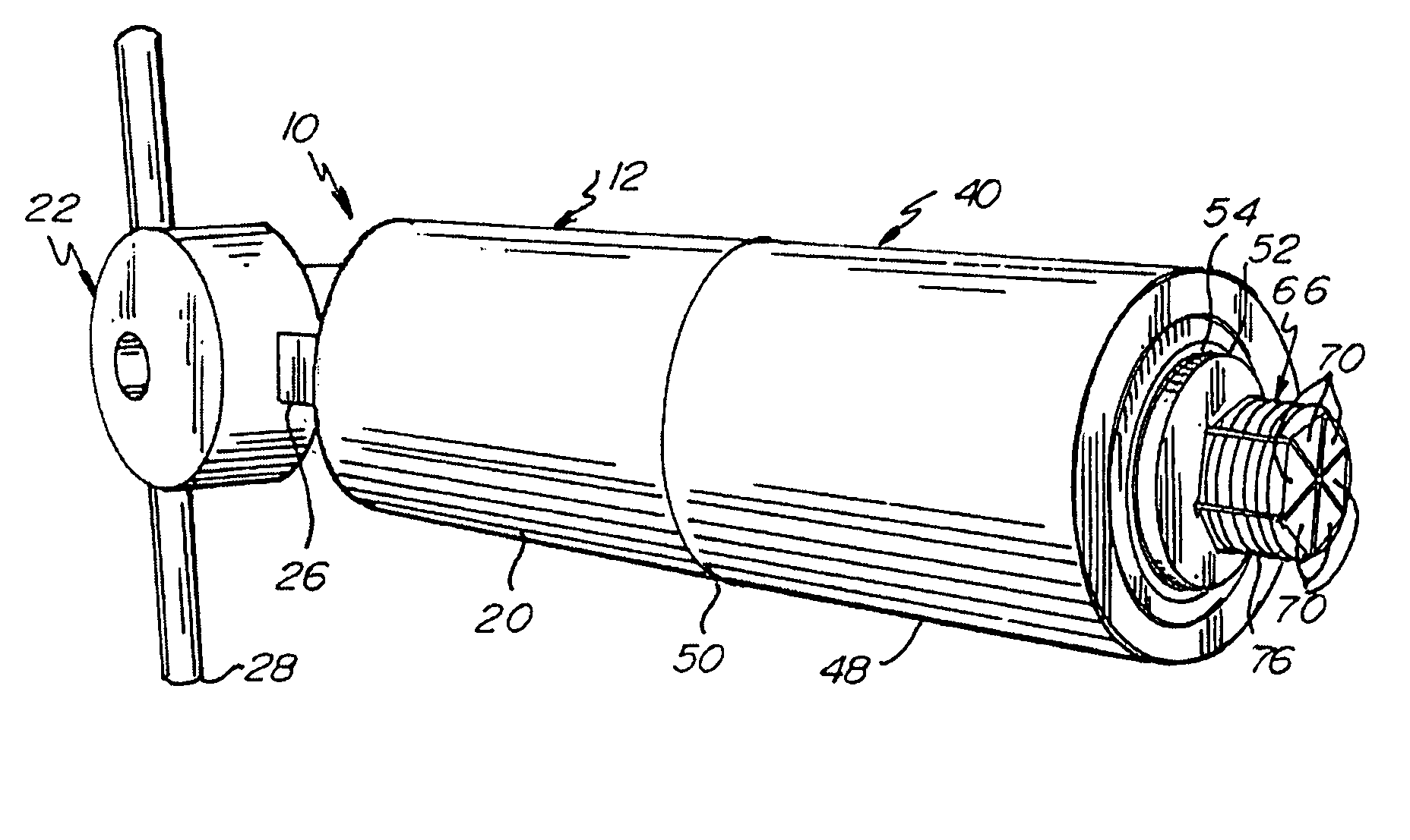
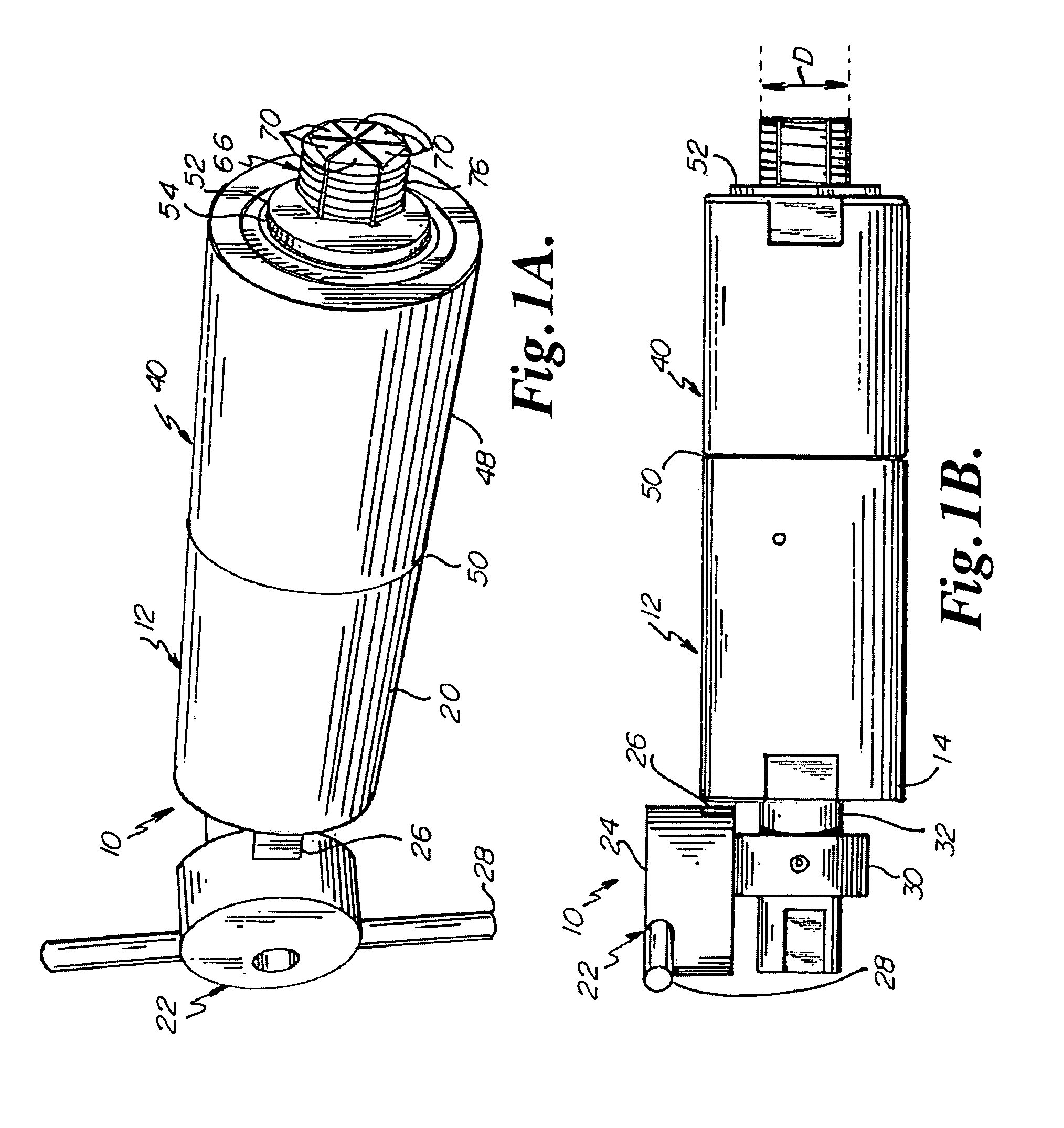
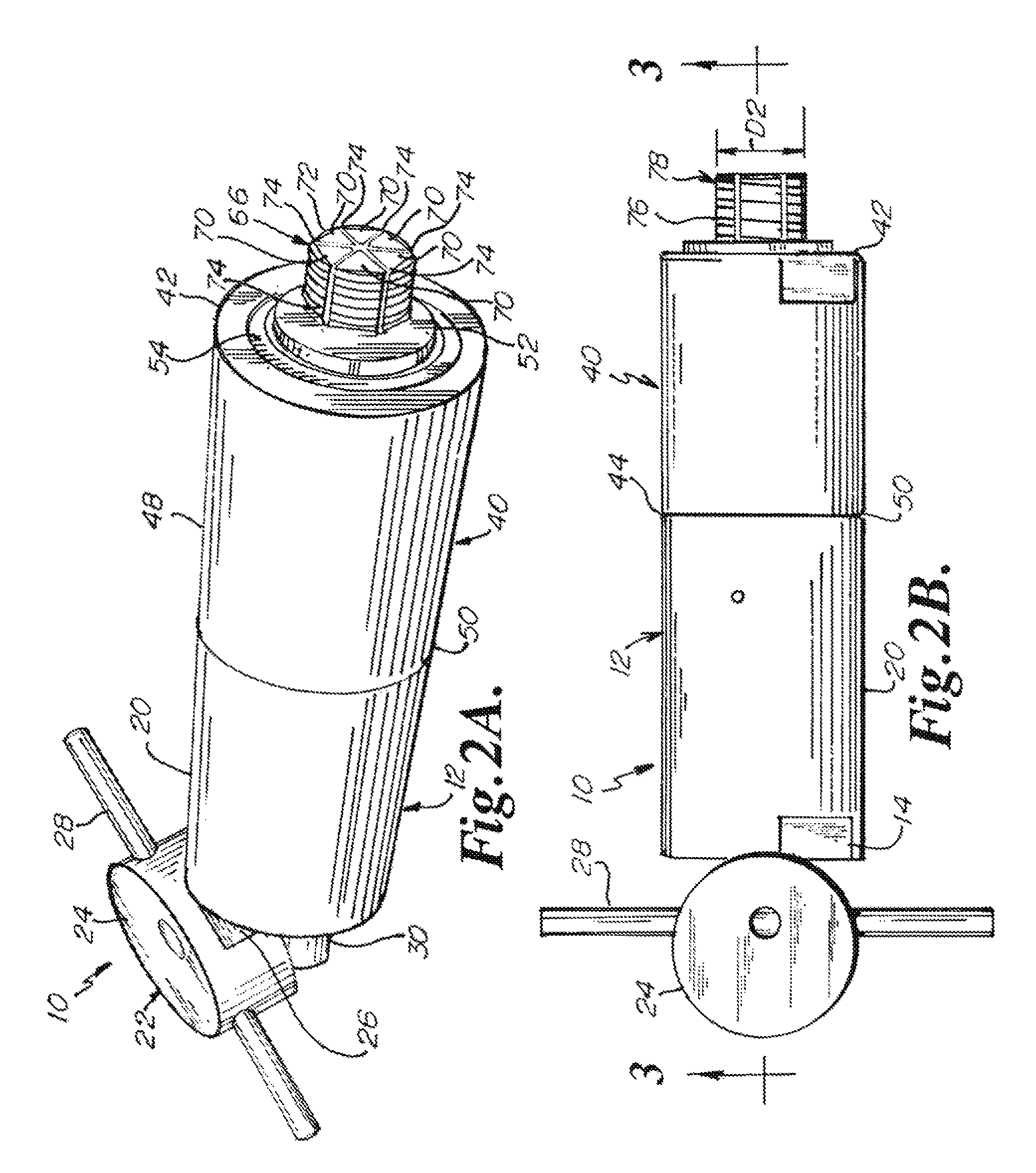
[0044]Preferred embodiments of the present invention are illustrated in FIGS. 1-12B. Referring in particular now to FIGS. 1-3 and 7-8, one embodiment of a hydrostatic testing tool 10 includes an actuator unit 12 interconnected to an article or container-engaging head 40. The head 40 is a generally cylindrical structure that includes a front end 42, a rear end 44 and an attachment body 48 which threads onto the actuator unit 12 at junction 50. The actuator unit 12 has a rear end 14 and at the rear end 14 is an inlet aperture 16 that is sealably attached in any known way to a source of high-pressurized fluid material (not shown), preferably liquid, for testing. It should be understood that although the inlet aperture 16 is described as for receiving liquid, the testing tool 10 of the present invention will work with gases as well. The pressurized liquid entering inlet aperture 16 flows along a central channel 18 in a direction towards the head 40. It will be appreciated that the conta...


PUM

PropertyMeasurementUnit
internal volumeaaaaaaaaaa
pressuresaaaaaaaaaa
rotationaaaaaaaaaa

Abstract

A hydrostatic testing tool for testing containers, hoses or the like under high pressures. The testing tool having a coupling that threadably engages a threaded aperture of a test container without having to be rotated into the threaded aperture. The hydrostatic testing tool may be hooked up to a source of pressurized medium and the tool includes a container-engaging head having a plurality of collet segments that each have a threaded surface that can expand radially outward, partially due to the force of the pressurized medium, to engage a threaded aperture of the test container, allowing for the formation of a liquid and / or gas tight seal under high pressures. The testing tool further includes an actuating unit connected to the head that controls the movement of the collet segments with a piston or the like.

Description

RELATED APPLICATION[0001]The present application is related to and claims priority to U.S. Patent Application Ser. No. 60 / 888,624, filed Feb. 7, 2007, currently pending, and is titled HYDROSTATIC TESTING TOOL AND METHOD OF USE, wherein the aforementioned application is incorporated herein by reference.BACKGROUND OF THE INVENTION[0002]1. Field of the Invention[0003]The present invention relates generally to a hydrostatic testing tool. Particularly, the present invention relates to a hydrostatic testing tool having a coupling that threadably engages a threaded aperture of a test article without having to be rotated into the threaded aperture. More particularly, the present invention relates to a hydrostatic testing tool, which has a plurality of threaded collet segments that can expand radially outward to engage a threaded aperture of a test article to form a junction between the testing tool and the test article, which provides a liquid tight seal when the testing tool is operatively...

Claims


Application Information

Patent Timeline
Patent Type & Authority Patents(United States)
IPC IPC(8): G01N9/12
CPCG01M13/005G01N3/12Y10T29/49996Y10T279/1008G01N2033/0081
Inventor SMIDA, CHARLES R.MORSE, DARRELL E.LOZINSKI, DANIEL L.
Owner AIRMO INC
Why Eureka
Try Eureka