
Seals and methods for sealing coaxial cable connectors and terminals

a technology of coaxial cable and connector, applied in the direction of coupling device connection, coupling base/case, two-part coupling device, etc., can solve the problems of reducing the installation procedure, affecting the installation process, and exposing seams and/or internal voids, so as to reduce the force required to slid

Active Publication Date: 2011-05-10
PPC BROADBAND INC
View PDF11 Cites 30 Cited by
  • Summary
  • Abstract
  • Description
  • Claims
  • Application Information

AI Technical Summary

Benefits of technology

[0010]A seal member is disclosed herein for forming a seal at the juncture of a coaxial cable connector and a terminal, wherein the coaxial cable connector is secured to an end of a coaxial cable. The seal member can be advantageously mounted on the connector to form a seal member / connector assembly, or seal-connector assembly. The connector of the seal-connector assembly can be secured to the coaxial cable prior to connection of the seal-connector assembly with the terminal. The seal member can be slid over the connector and into contact with the terminal while maintaining contact with the connector. Preferably, the entire seal member is slid over, i.e. translates over, the connector and into contact with the terminal. The seal member can thus provide a 360° environmental seal around the connector-terminal junction. In some embodiments, the seal member is slidably mounted on a coupler, such as a nut, of the connector. The seal member is generally tubular with an inner surface having a first inner diameter, located at least at a first axial position on the seal member, which is smaller than an outer diameter of the terminal, and the inner surface having a second inner diameter, located at least at a second axial position on the seal member, which is smaller than an outer diameter of the terminal, wherein the first and second diameters may be equal or different, and wherein the first and second axial positions may be equal or different. In the deployed position, the inner surface of the seal member contacts the connector and forms a 360° seal thereat, and the inner surface of the seal member contacts the terminal and forms a 360° seal thereat. In some embodiments, the seal member has a uniform tubular wall thickness. In other embodiments, the seal member has a variable thickness wall; in some of these embodiments, the seal member has a first portion having a first wall thickness which is larger (i.e. thicker) than the wall thickness of another portion of the seal member, and preferably the first portion is disposed at or proximate a front end of the seal member, wherein “front” is the direction in which the seal member would face toward the terminal and “back” is the direction in which the seal member would face toward the coaxial cable, wherein such first portion can be advantageously provided to reduce the force required to slide the seal member over the coaxial connector. In accordance with one embodiment of the present invention, a method of connecting a coaxial connector and a terminal includes providing a coaxial connector comprising a coupler, the coupler having a seal member in contacting relationship with the coupler such that the seal member is coaxial with the coupler about a longitudinal axis, affixing the coupler to the terminal and after the coupler is affixed to the terminal, sliding the seal member longitudinally toward, and into contact with, the terminal.

Problems solved by technology

For various reasons, the foregoing attempts have yielded less than satisfactory results.
For example, attempts at encapsulating the connectors with tapes, shrink wrappings and plastic or rubber cements are too prone to installation errors, which can result in exposed seams and / or internal voids where moisture can collect and eventually penetrate to the cable junction.
Moreover, shrink wrappings require the use of heat or chemicals which further complicate installation procedures.
Cements require time to set up and cure, thus prolonging and complicating installation procedures.
The use of sealing components such as externally applied flexible boots and / or grommets can result in internal voids where moisture can collect.
In addition, installation of tight fitting seal rings is difficult and therefore many times is avoided.
Subsequent removal of tight fitting seal rings after a lengthy period of service can be even more difficult than installation.
Additionally, existing seal rings are limited in use by the length of the terminal port on which they are installed.
However, issues arise with this arrangement in that such seal rings cover substantially most of the threads on the appliance port and require that at least a portion of the corresponding cable connector coupler engage the seal ring while engaging the port threads.
This engagement during tightening can cause difficulty in turning the connector coupler, thus making the connector hard to install.

Method used


Image

  • Seals and methods for sealing coaxial cable connectors and terminals
  • Seals and methods for sealing coaxial cable connectors and terminals
  • Seals and methods for sealing coaxial cable connectors and terminals

Examples


Embodiment Construction

[0034]Reference will now be made in detail to the embodiment(s) of the invention, examples of which are illustrated in the accompanying drawings. Whenever possible, the same reference numerals will be used throughout the drawings to refer to the same or like parts.

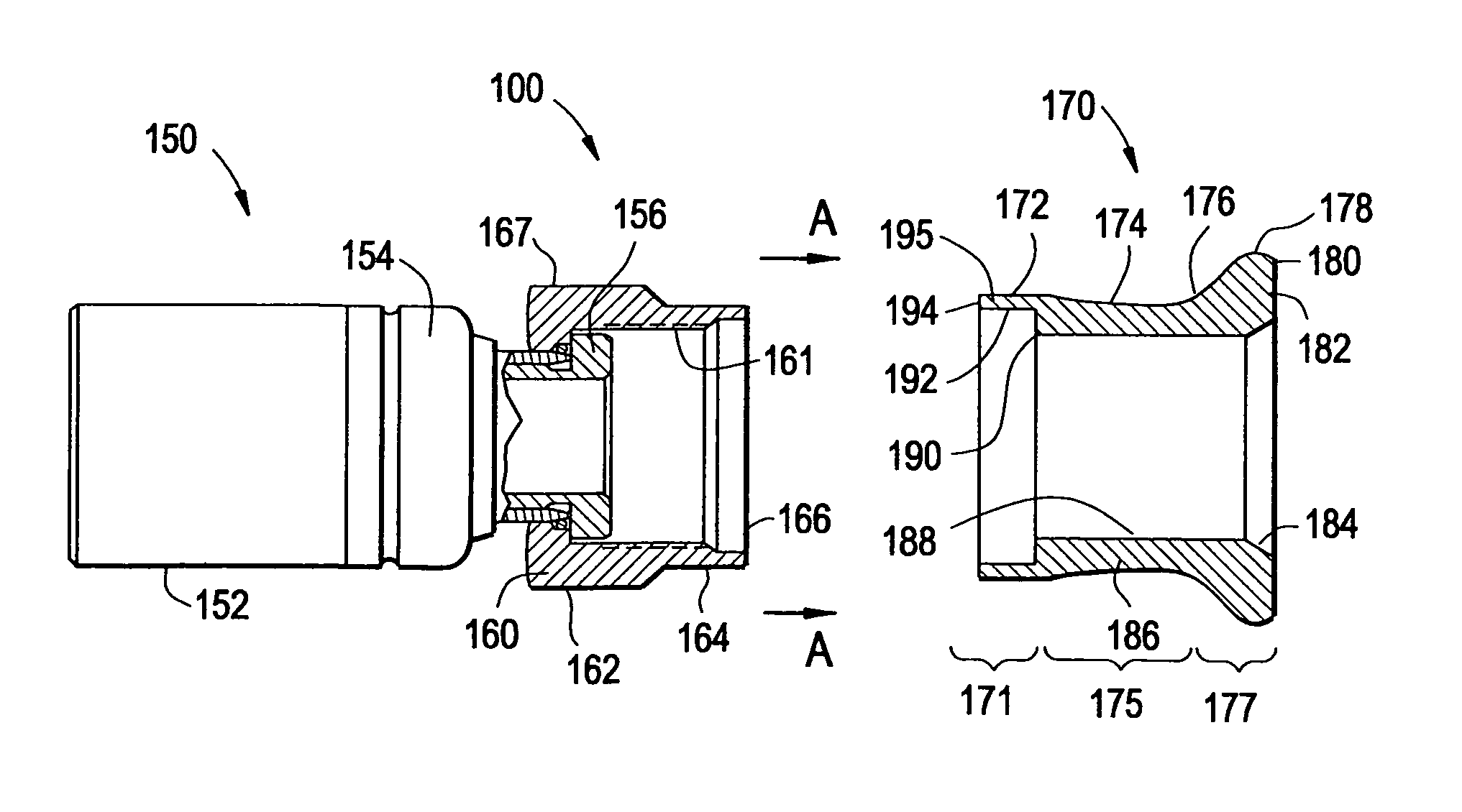
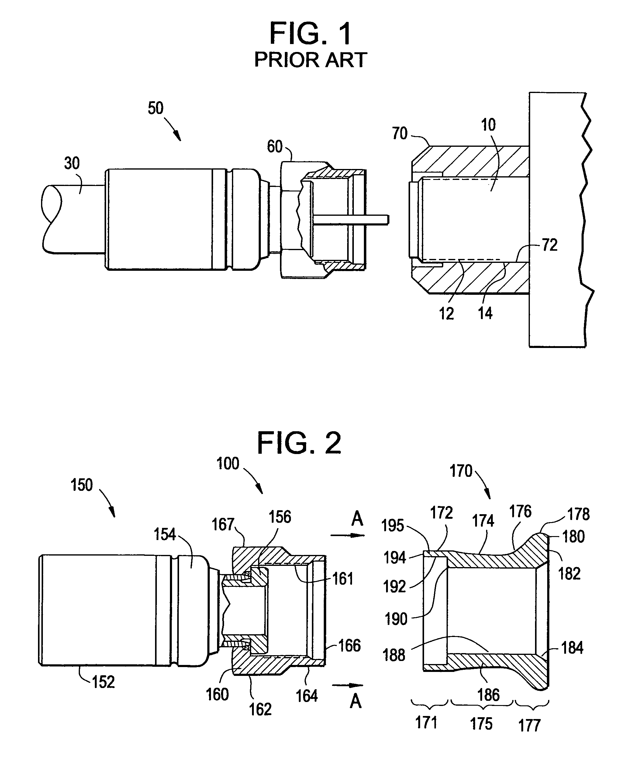
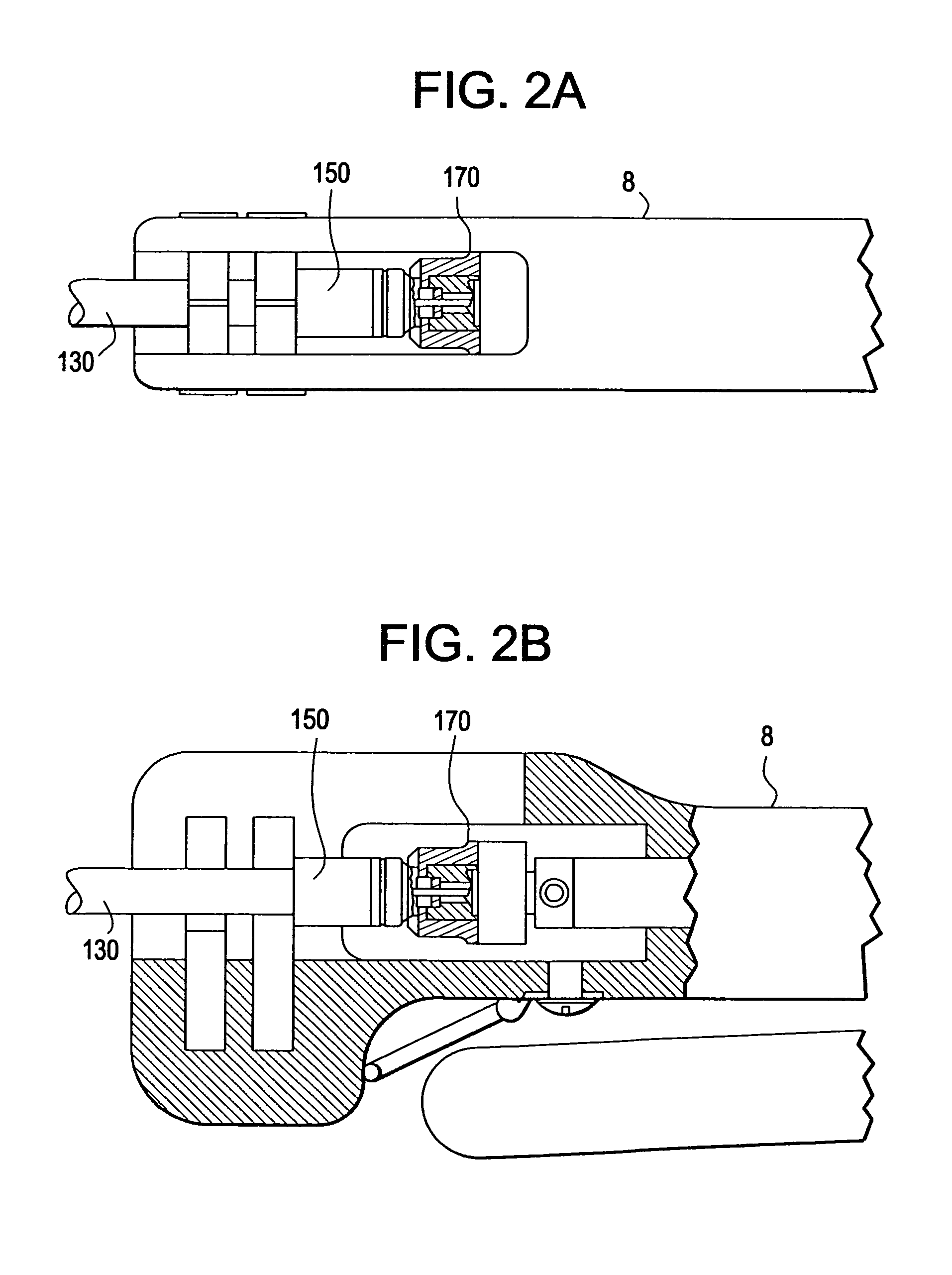
[0035]Referring to FIG. 2, an exemplary embodiment of a seal assembly 100 comprising a coaxial cable connector 150 and seal member 170 of the present invention is illustrated in an exploded form. As described more fully herein, seal members of the present invention can be used to seal a junction between a connector and a terminal in applications such as television cables / terminals. As illustrated in FIG. 2, an exemplary connector 150 (for attachment to the coaxial cable 130 of FIG. 2A) includes a fastening member 152, a body 154, a post 156 and a coupler 160. Coupler 160 can include threads 161 for mating with a terminal, an external surface 162, a sealing surface 164 and an inner bore 166. At least a portion of the extern...


PUM


Abstract

Methods of connecting a coaxial connector and a terminal include providing a coaxial connector with a coupler, the coupler having a seal member in contacting relationship with the coupler such that the seal member is coaxial with the coupler about a longitudinal axis, affixing the coupler to the terminal and after the coupler is affixed to the terminal, sliding the seal member longitudinally toward, and into contact with, the terminal. When in a tightening position, the seal member covers an engagement surface of the coupler, and wherein when in a deployed position, the seal member contacts at least a portion of the terminal.

Description

CROSS-REFERENCE TO RELATED APPLICATIONS[0001]This application claims the benefit of, and priority to U.S. Provisional Application No. 60 / 934,876, filed Jun. 15, 2007, the content of which is relied upon and incorporated herein by reference in its entirety.BACKGROUND OF THE INVENTION[0002]1. Field of the Invention[0003]The present invention relates to seal members for coaxial cable connectors, and particularly to seal members for sealing junctions between coaxial cable connectors and terminals.[0004]2. Technical Background[0005]Coaxial cable connectors such as Type F connectors are used to attach a coaxial cable to another object such as an appliance having a terminal adapted to engage the connector. Such connectors must be attached to a coaxial cable using various cable preparation techniques and installation tools. Cable preparation typically requires removal of a portion of the cable jacket, braid, outer conductor and core to expose the cable center conductor. Another portion of t...

Claims


Application Information

Patent Timeline
Patent Type & Authority Patents(United States)
IPC IPC(8): H01R13/52
CPCH01R13/5219H01R24/40H01R2103/00
Inventor BURRIS, DONALD ANDREWWOOD, KENNETH STEVEN
Owner PPC BROADBAND INC
Learn More