Windshield wiping device for a motor vehicle

a technology for wiping devices and motor vehicles, which is applied in the direction of vehicle cleaning, traffic signals, ways, etc., can solve the problems of pedestrian injuries, engine hood deformation is only able to deform relatively little in this area, and pedestrian injuries are to be expected. , to achieve the effect of reducing the cross-section

Inactive Publication Date: 2011-05-17
ROBERT BOSCH GMBH
View PDF16 Cites 33 Cited by
  • Summary
  • Abstract
  • Description
  • Claims
  • Application Information

AI Technical Summary

Benefits of technology

[0004]The object of the invention is improving a windshield wiper device of the type cited at the outset in such a way that in the future the attachment of the molded tube to the holding element and / or to the stub can be realized in a manner that saves more material.
[0005]The invention attains the imposed objective with a windshield wiper device for a motor vehicle with at least one molded tube to accommodate a drive shaft to drive at least one wiper arm, wherein the at least one molded tube can be attached to a holding element that can be connected to the body, and to a stub accommodating a mounting plate tube. According to the invention, the windshield wiper device is characterized in that connecting bridges are provided to attach the at least one molded tube to the holding element and / or to the stub. The connecting bridges are relatively thin and therefore material-saving parts. As a result, they serve to reduce weight and costs. The connecting bridges are structural elements that are simple to realize in terms of design, which, particularly in the case of a plastic design, can be realized in an economical manner in terms of the requirements imposed on them.
[0007]In the case of a development of the invention, an impact force acting on the at least one molded tube and therefore on the connecting bridges can be strengthened by a lever arm design. Because of the lever arm design, the deforming or breaking off of the connecting bridges is guaranteed even in the case of small forces, thereby increasing the pedestrian's safety.
[0010]In a preferred embodiment of the invention, the connecting bridges can be arranged like elbow levers. As a result, the great stress can build up in the connecting bridges even with small deformation paths, whereby the weaker connecting bridges fail relatively quickly and thereby guarantee continued movement of the at least one molded tube out of the impact area.
[0012]Furthermore, the invention includes a windshield wiper device for a motor vehicle with at least one molded tube to accommodate a drive shaft to drive at least one wiper arm, wherein the at least one molded tube can be attached to a holding element that can be, connected to the body, and, in accordance with the invention, the holding element features a cross-section reduction in the area of the attachment of the at least one molded tube to the holding element. Consequently, even with low stress the molded tube can be bent or broken together with the holding element to which it is attached via an impact in the area of the cross-section reduction.

Problems solved by technology

In particular, inflexible, hard parts under the engine hood frequently lead to severe injuries when a pedestrian impacts a vehicle.
However, as a rule a drive shaft for the windshield wiper device projects out of the molded tube and normally has only a distance of 10 mm to the hood.
In a collision, if the head of a pedestrian impacts the area of the molded tube, the engine hood is only able to deform relatively little in this area.
Consequently, severe injuries to the pedestrian are to be expected.
This proposed solution has the disadvantage, however, that a lot of material is present, particularly in the area of the attachment of the holding element and the stub to the molded tube.

Method used


Image

  • Windshield wiping device for a motor vehicle
  • Windshield wiping device for a motor vehicle
  • Windshield wiping device for a motor vehicle

Examples


Embodiment Construction

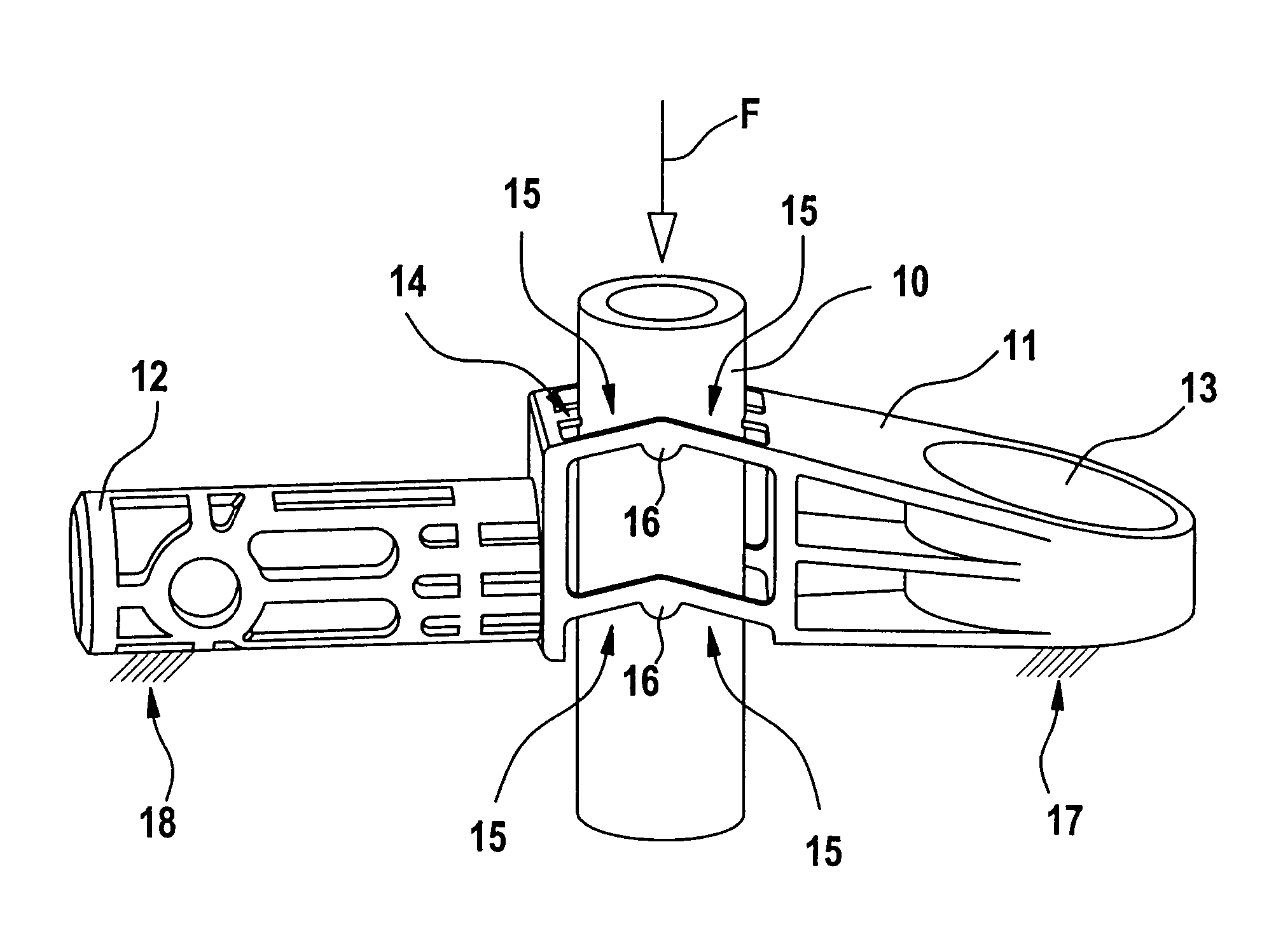
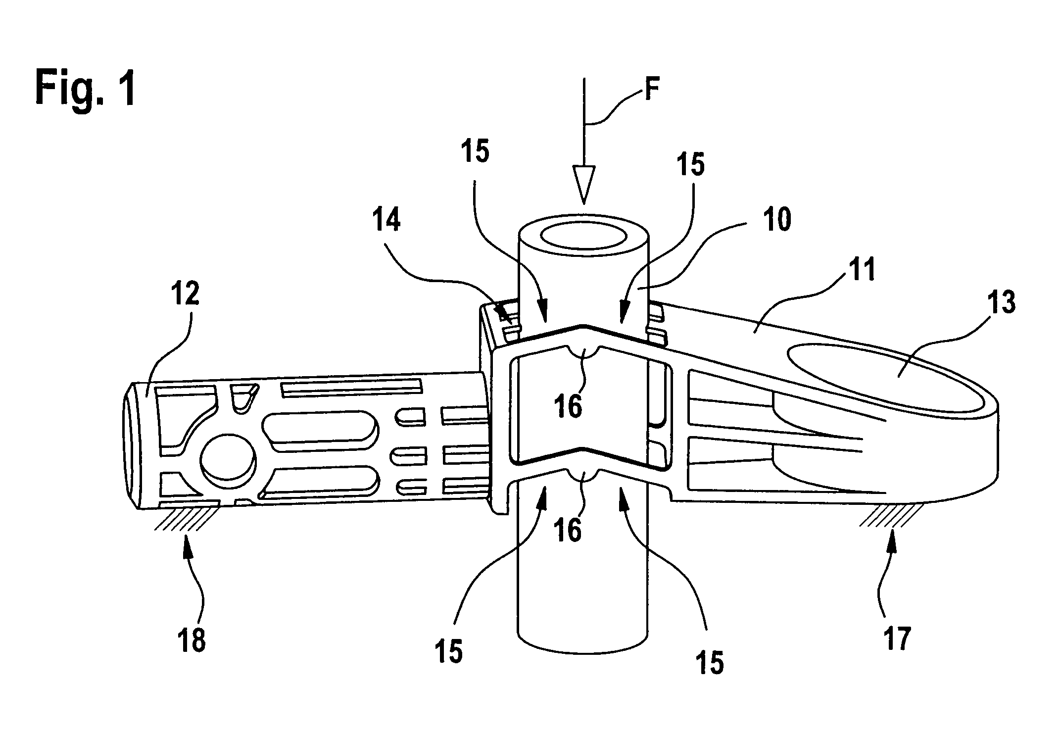
[0019]FIG. 1 shows a molded tube 10 into which a drive shaft (not shown here in more detail) to drive a wiper arm (also not shown here in more detail) can be inserted. A holding element 11 and a stub 12 are attached to the molded tube 10. The holding element 11 features a receptacle opening 13 into which the fastening means (not shown here) for fastening the holding element 11 to a body (also not shown here) can be introduced. A solid point of fixation 17 is created by the connection of the holding element 11 to the body. A mounting plate tube (also not shown) can be crimped onto the stub 12 so that the stub 12 features a solid point of fixation 18. The holding element 11 and the stub 12 are connected to the molded tube 10 via bridges 14 and 15. The bridges 15 each feature an elbow 16, which is connected to the molded tube 10. If a force F, e.g., an impact force in the case of the impact of a pedestrian, acts on the molded tube 10, the molded tube 10 then moves in the direction of f...


PUM


Abstract

Windshield wiper device for a motor vehicle with at least one molded tube (10) to accommodate a drive shaft to drive at least one wiper arm, wherein the at least one molded tube (10) can be attached to a holding element (11) that can be connected to the body, and to a stub (12) accommodating a mounting plate tube, and connecting bridges (14, 15) are provided to attach the at least one molded tube (10) to the holding element (11) and / or to the stub (12).

Description

BACKGROUND OF THE INVENTION[0001]The invention relates to a windshield wiper device for a motor vehicle with at least one molded tube to accommodate a drive shaft to drive at least one wiper arm, wherein the at least one molded tube can be attached to a holding element that can be connected to the body, and to a stub accommodating a mounting plate tube.[0002]Pedestrians are completely unprotected in collisions with vehicles. In particular, inflexible, hard parts under the engine hood frequently lead to severe injuries when a pedestrian impacts a vehicle. The windshield wiper device is located in an area where a pedestrian frequently impacts in the case of a collision with a vehicle. In order to minimize the risk of injury, vehicle manufacturers are required to maintain a minimum distance of 65 to 85 mm between the engine hood and the wiper drive. However, as a rule a drive shaft for the windshield wiper device projects out of the molded tube and normally has only a distance of 10 mm...

Claims


Application Information

Patent Timeline
Patent Type & Authority Patents(United States)
IPC IPC(8): B60S1/06B60S1/24B60S1/04B60S1/34
CPCB60S1/34B60S1/0488B60S1/0425Y10T403/11F16B2200/63B60S1/04B60S1/32
Inventor KRAUS, ACHIMDIETRICH, JAN
Owner ROBERT BOSCH GMBH
Why Eureka
Try Eureka