Eureka AIR delivers breakthrough ideas for toughest innovation challenges, trusted by R&D personnel around the world.

Integrated curtain wall and wireway distribution system

a technology of wireway distribution system and integrated curtain wall, which is applied in the field of curtain wall, can solve the problems of increasing installation labor, limited opportunity to provide power and/or data to the predominate, and destroying the aesthetic appeal created by the curtain wall

Active Publication Date: 2011-05-17
MERICA ANNE ELLIOTT
View PDF22 Cites 74 Cited by
  • Summary
  • Abstract
  • Description
  • Claims
  • Application Information

AI Technical Summary

Problems solved by technology

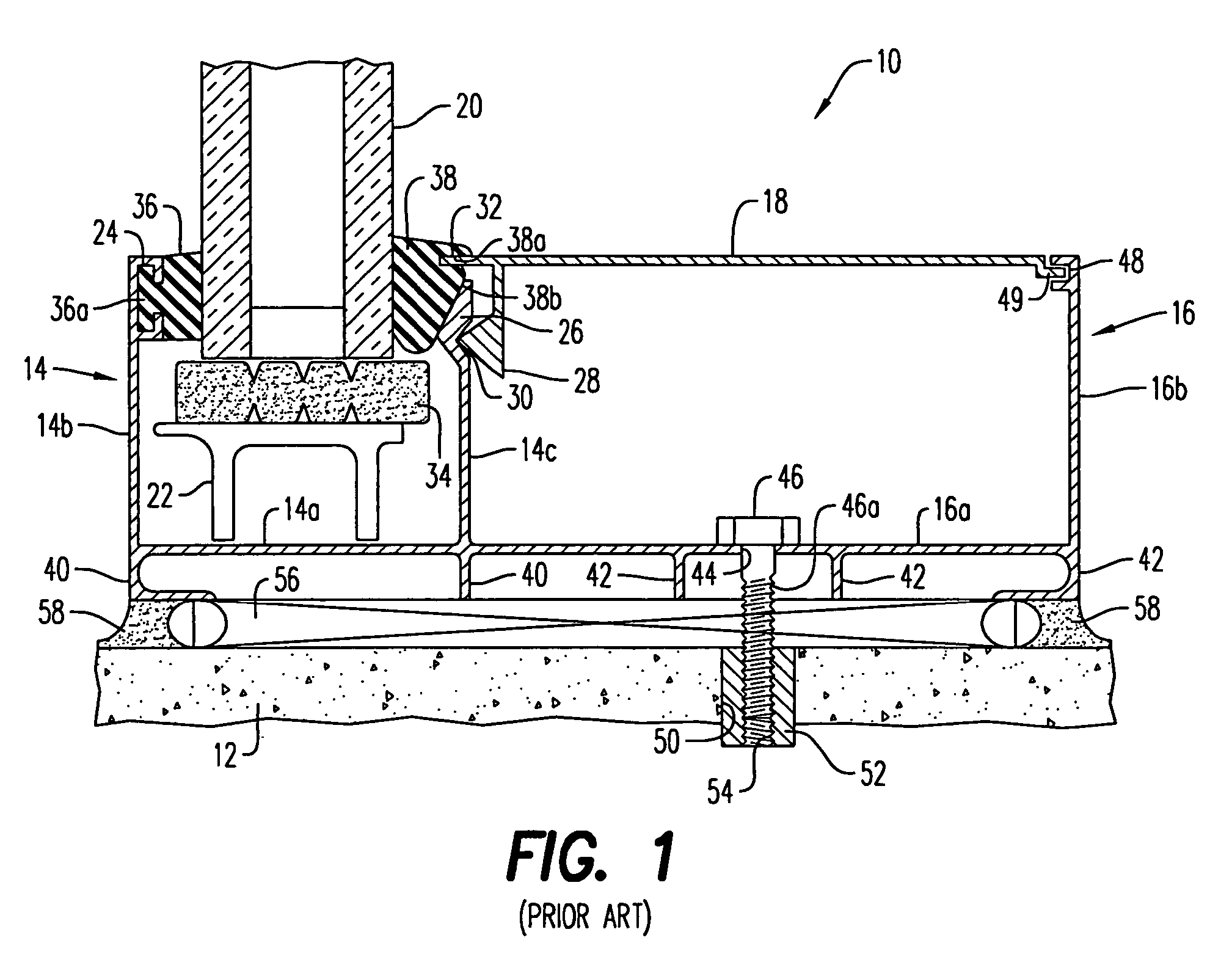
While such systems, and other conventional curtain walls, have proved to be reliable commercial building systems, they suffer from several drawbacks.
One particular drawback of these types of systems is the limited opportunity to provide power and / or data to the predominate exterior walls of the building, unless a separate metal stud and finish partition, with conventional conduits and outlets, is created between or under the window system, which thereby requires increased labor for installation and destroys the aesthetic appeal created by the curtain wall and increased glass area.

Method used


Image

  • Integrated curtain wall and wireway distribution system
  • Integrated curtain wall and wireway distribution system
  • Integrated curtain wall and wireway distribution system

Examples


Embodiment Construction

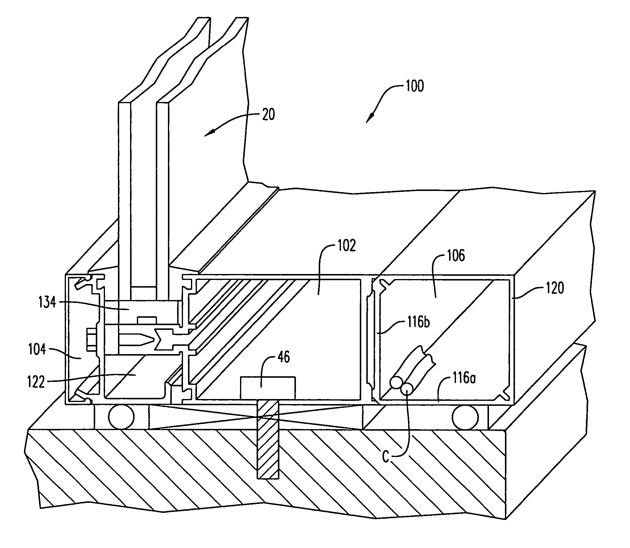
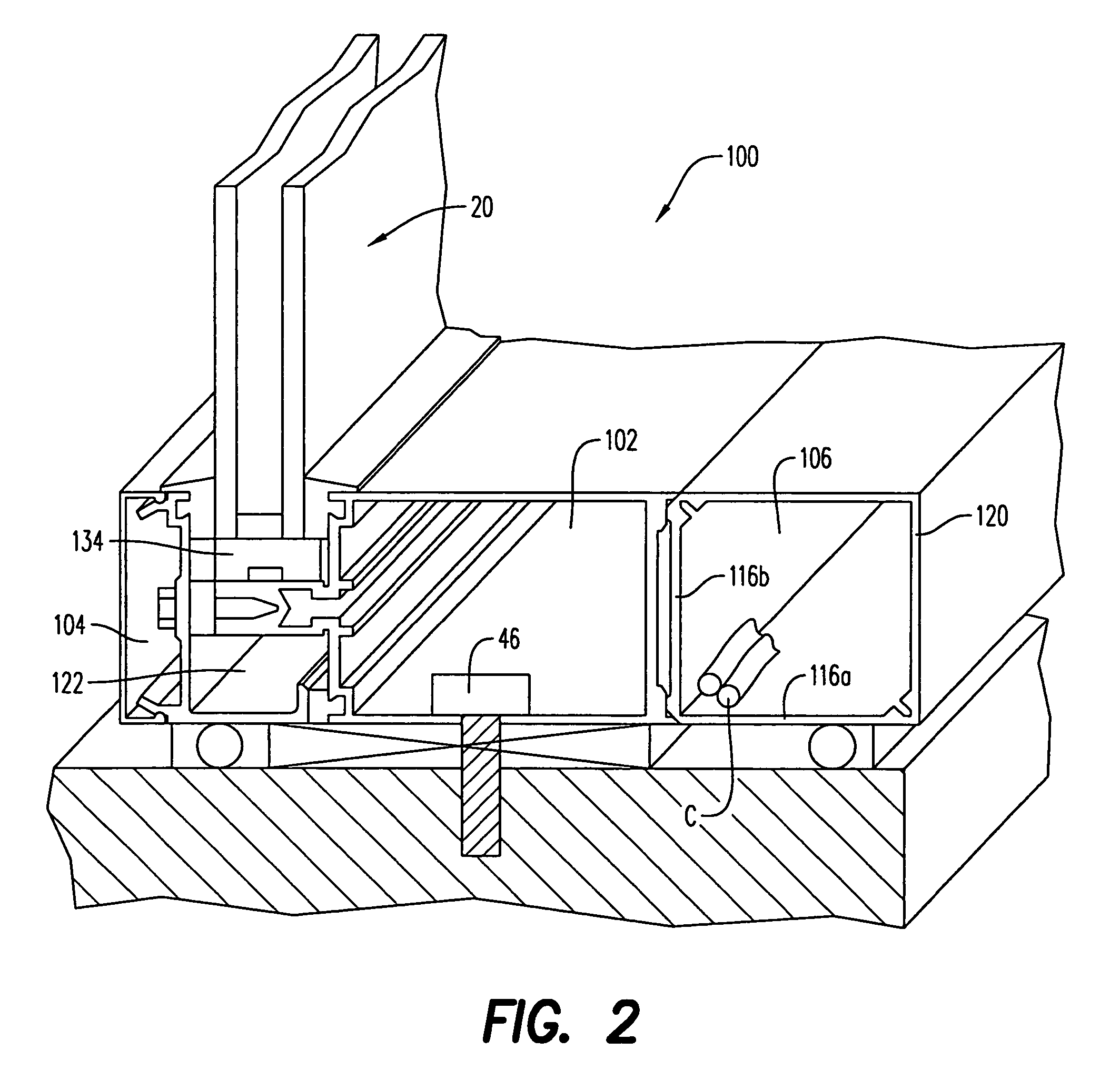
[0016]Referring to FIG. 2, the sill structure of the present invention is shown generally by reference numeral 100. Preferably, the glazed panel 20 is supported on a platform 122 via a support pad 134 or similar structure, similar to the previously described prior art structure of FIG. 1. Further, the sill structure 100 includes the same or a similar type of upwardly open channel arrangement for receiving the panel and its platform, such as described previously with reference to FIG. 1. The specific construction of the sill structure may vary from that shown in the illustrated embodiments or described as the prior art, however, without departing from the scope of the present invention. A channel 102 preferably spaced inwardly of the glazed panel 20 serves to provide access to the anchor bolt 46, in the same or similar manner as described above with reference to the prior art embodiment. The sill structure 100 as illustrated discloses a standard type of mullion used for supporting a ...


PUM


Abstract

A curtain wall including an extruded aluminum sill having a first channel for receiving a glazed panel, a sill anchor / access portion for securing the sill to a poured concrete slab or slab wall, and toward the interior side of the sill, a wireway is defined in part by the sill and in part by a wireway cover for concealing power and / or data / telecommunication cables. The wireway cover may also include outlet devices or plugs arranged in a longitudinally spaced relationship.

Description

TECHNICAL FIELD[0001]The present invention pertains to curtain walls used for building exteriors and, more particularly, to an improved curtain wall having a wireway distribution system integrated therewith.BACKGROUND ART[0002]Curtain walls are typically constructed of extruded aluminum frame support members having generally U-shaped channels for supporting a plurality of panel members that serve as the exterior of a building. Such panel members are most often panes of glass, but other paneled building materials such as aluminum, granite, slate, or concrete are also utilized. Such panel members are often of identical size and shape. However, near doors, opening windows, or other access points into the building, panel members of different sizes and shapes may be utilized.[0003]More specifically, such curtain walls generally include a horizontal sill member having an upwardly facing U-shaped channel at the bottom of a wall section, a horizontal head member having a downwardly facing U...

Claims


Application Information

Patent Timeline
Patent Type & Authority Patents(United States)
IPC IPC(8): E04C2/52E04H14/00E04H5/00E04B2/96H02G3/04
CPCE04B2/90H02G3/0425E06B7/28E04B2/96
Inventor MERICA, ANNE ELLIOTT
Owner MERICA ANNE ELLIOTT
Why Eureka
Eureka Blog
Learn More