Ribbon cartridge and printing apparatus

a printing apparatus and cartridge technology, applied in the field of cartridges, can solve the problems of ink ribbon jam, ink ribbon may slip out of the slit, derail from the ribbon guide, unstable ink ribbon running path, etc., to prevent the derailing of ink ribbon, prevent the occurrence of ribbon jam, and stable ink ribbon running

Inactive Publication Date: 2011-05-17
SEIKO EPSON CORP
View PDF11 Cites 84 Cited by
  • Summary
  • Abstract
  • Description
  • Claims
  • Application Information

AI Technical Summary

Benefits of technology

[0007]The present construction is contrived in consideration of the above-mentioned problems, and an object is to provide a ribbon cartridge and a printing apparatus capable of preventing an ink ribbon from derailing while enabling stable running thereof.
[0009]Since the cutout through which the ink ribbon is inserted is formed at one of the pair of plates so as to surround the bar member, the cutout is provided with a cutout portion extending with a predetermined slope relative to the running direction of the ink ribbon. Thus, it is possible to prevent the ink ribbon from derailing from the ribbon guide even when a vertical directional force is applied to the ink ribbon in the course of the running thereof.
[0010]Additionally, since the pair of plates does not have a cantilever shape, the running path of the ink ribbon does not become unstable. Thus, it is possible to enable stable running of the ink ribbon and thus to prevent occurrence of a ribbon jam.
[0012]With such a configuration, since a plurality of the bar members are provided to the ribbon cartridge, even when a force is applied to the bar member in the direction in which the transfer surface of the ink ribbon presses the bar members, the load applied to the bar members is distributed to each bar member. Thus, it is possible to prevent bending of the bar members and thus to enable a stable running of the ink ribbon.
[0014]With such a configuration, it is possible to prevent the ink ribbon from derailing from the cutout in a secure manner.
[0018]With such a configuration, it is possible to smoothly guide the ink ribbon that enters in the ribbon guide or exits from the ribbon guide.

Problems solved by technology

However, when the slit is formed so as to extend along the running direction of the ink ribbon, the ink ribbon may slip out of the slit and derail from the ribbon guide when moving in the vertical direction perpendicular to the running direction in the course of running the ink ribbon.
As a result, the running path of the ink ribbon becomes unstable, and a ribbon jam may occur.

Method used


Image

  • Ribbon cartridge and printing apparatus
  • Ribbon cartridge and printing apparatus
  • Ribbon cartridge and printing apparatus

Examples


Embodiment Construction

[0036]Hereinafter, an embodiment will be described with reference to the drawings. In the following embodiment, an example will be described in which the device is applied to a dot-impact printer.

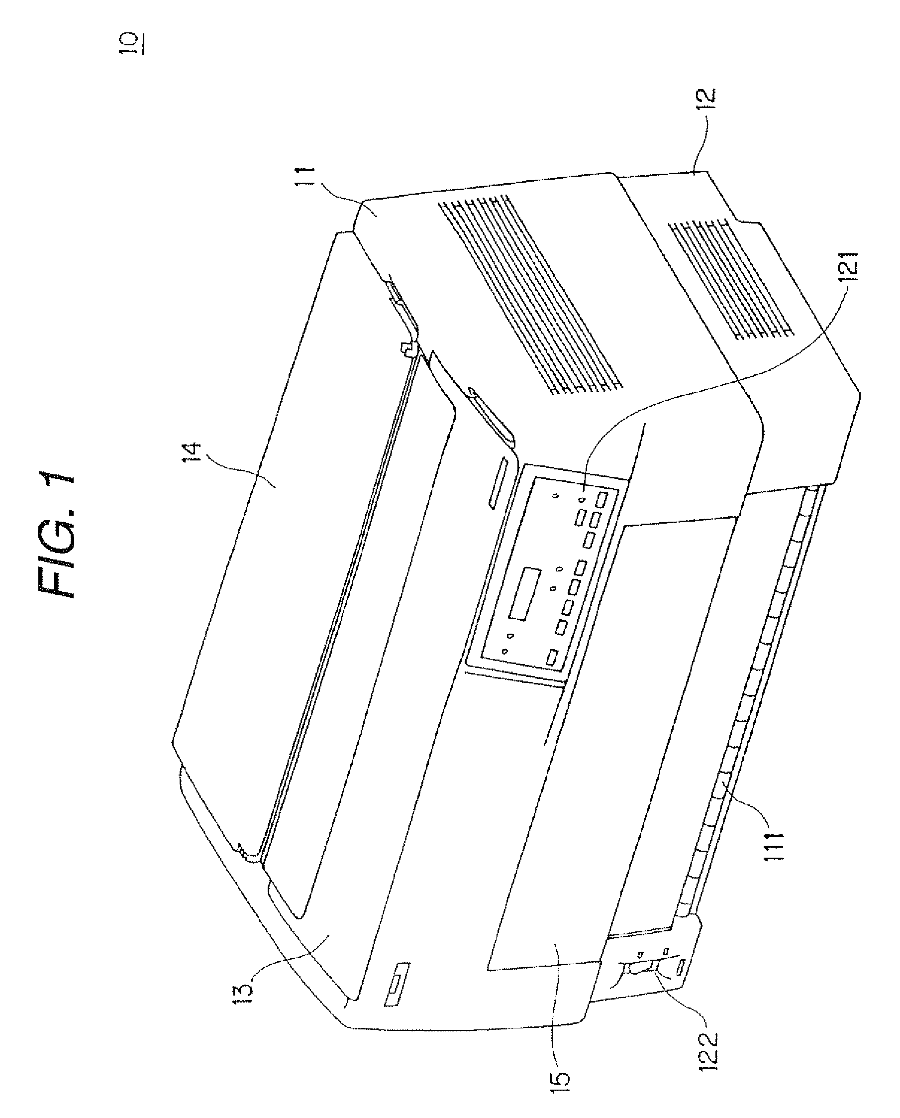
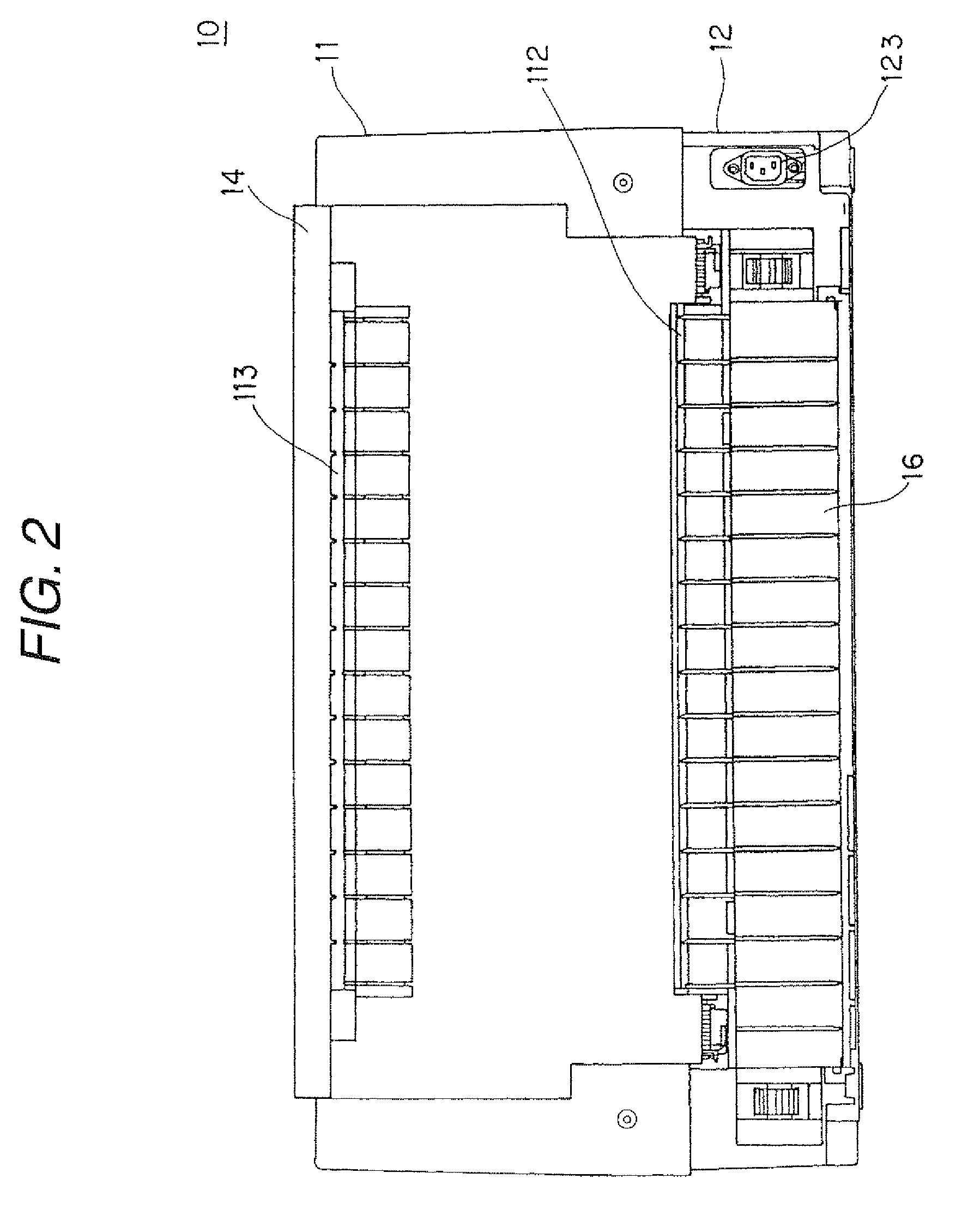
[0037]FIG. 1 is an external perspective view showing a dot-impact printer 10. FIG. 2 is a rear elevation view showing the dot-impact printer 10. FIG. 3 is a perspective view showing a configuration of a printer part 20 provided in the dot-impact printer 10. FIG. 4 is a sectional view showing the printer part 20 taken along A-A′ line in FIG. 3. FIG. 5 is a top plan view showing the dot-impact printer 10 when an upper-side cover 13 is opened. FIG. 6 is a top plan view showing the dot-impact printer 10 when a ribbon cartridge 50 is mounted thereon after opening the upper-side cover 13.

[0038]The dot-impact printer 10 includes a print head 30 having a plurality of print wires (not shown), and is configured to print images including text on a print surface of a print sheet by allowing a print hea...


PUM


Abstract

A ribbon guide includes a pair of upper and lower plates for limiting upper and lower ends of an ink ribbon. A ribbon guide plate is disposed between the pair of upper and lower plates so as to guide a non-transfer surface of the ink ribbon. Ribbon press bars are suspended between the pair of upper and lower plates so as to guide a transfer surface of the ink ribbon. Cutouts through which the ink ribbon is inserted are formed at the lower plate so as to surround lower end portions of the ribbon press bars.

Description

[0001]This application is the U.S. national phase of International Application No. PCT / JP2006 / 303445 filed 24 Feb. 2006 which designated the U.S. and claims priority to Japanese Patent Application No. 2005-049038 filed 24 Feb. 2005, the entire contents of each of which are hereby incorporated by reference.TECHNICAL FIELD[0002]The present invention relates to a ribbon cartridge having a ribbon guide for guiding a running path of an ink ribbon and a printing apparatus having the ribbon cartridge, and more particularly, to an arrangement for stabilizing a running path of an ink ribbon.BACKGROUND ART[0003]In the past, as a printing apparatus, a dot-impact printer has been known which is provided with a print head for impacting on a print wire and an ink ribbon cartridge for receiving an ink ribbon, and in which an image is printed on a print sheet by allowing the print wire to collide with the print sheet on a platen where the ink ribbon sent from the ink ribbon cartridge is interposed ...

Claims


Application Information

Patent Timeline
Patent Type & Authority Patents(United States)
IPC IPC(8): B41J35/04
CPCB41J32/00B41J35/28B41J35/04B41J32/02
Inventor KUMAZAKI, MASAYUKISATO, SHINJIKAWAMURA, TAKUMI
Owner SEIKO EPSON CORP
Why Eureka
Try Eureka