Golf club head

a golf club and head technology, applied in the field of golf club head, can solve the problems of easy over-exceeding of the rebound coefficient limit of the golf rule, inability to obtain long carry, etc., and achieve the effect of reducing the center of gravity of the head, reducing carry, and reducing carry

Inactive Publication Date: 2011-05-17
BRIDGESTONE SPORTS
View PDF80 Cites 18 Cited by
  • Summary
  • Abstract
  • Description
  • Claims
  • Application Information

AI Technical Summary

Benefits of technology

[0006]According to the golf club head described in the aforementioned Japanese Unexamined Patent Application Publication No. 11-216203 and Japanese Unexamined Patent Application Publication No. 2004-41376, the center of gravity of the head can be lowered while the balance of inertia moment is maintained. However, in FIG. 2 of Japanese Unexamined Patent Application Publication No. 11-216203 and in Japanese Unexamined Patent Application Publication No. 2004-41376, since the thick part exists throughout the whole from the toe to the heel of the front edge of the sole part, the deflection of the face part at the ball hit time is restrained as a whole, so that the carry decreases. Also, in FIG. 4 of Japanese Unexamined Patent Application Publication No. 11-216203, since the thick part is provided separately on the sole side and the heel side, the deflection of the face part at the time of off-center hit is restrained, so that the carry decreases. In addition, since the deflection of the face part at the time when a ball is hit by the face center is great, the rebound coefficient easily exceeds the limit placed by the golf rules.
[0007]An object of the present invention is to provide a golf club head capable of increasing a carry on average even if being used by an amateur golfer who is prone to hit a ball by varied hit points across the clubface.
[0009]In the golf club head in accordance with the present invention, which is configured as described above, since the thick part is provided only in the central portion in the toe-heel direction of the cross corner portion between the sole part and the face part, the deflection near the center of the face part at the ball hit time is restrained, and the rebound coefficient can be kept within the range of the golf rules. In the present invention, since the thick part is provided on the face plate, a marked effect that the deflection near the center of the face plate at the ball hit time is restrained is achieved. In the present invention, on the toe side and the heel side of the face part, the thick part is not provided, and therefore the deflection at the ball hit time increases. Therefore, the carry of an off-center hit increases. However, on the toe side and the heel side of the face part, the rebound coefficient is low as compared with the face center. Therefore, even if the deflection increases, the rebound coefficient does not deviate from the golf rules. According to the present invention, the difference in carry between a face center hit and an off-center hit decreases, and therefore a stable fly can be obtained.

Problems solved by technology

In the case of what is called a high-rebound type golf club head utilizing the trampolining effect, although a long carry can be attained when a ball is hit by the face center, such a long carry cannot be obtained when the hit point deviates from the face center (off-center hit).
In addition, since the deflection of the face part at the time when a ball is hit by the face center is great, the rebound coefficient easily exceeds the limit placed by the golf rules.

Method used


Image

  • Golf club head
  • Golf club head
  • Golf club head

Examples


example 1

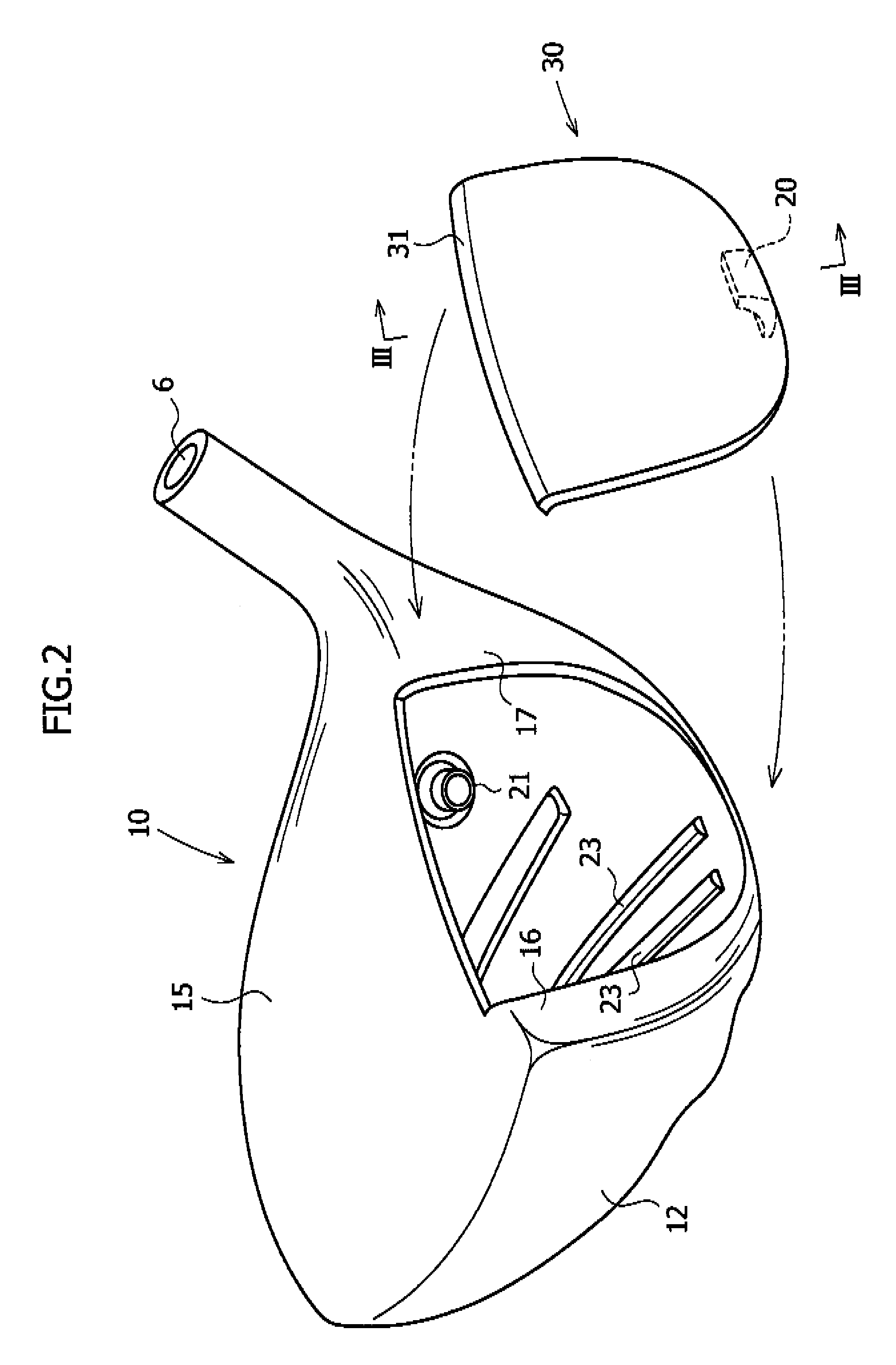
[0047]A golf club head having a volume of 460 cc, which was configured as shown in the figures, was manufactured. The head body 10 was formed of (Ti-6Al-4V) α-β type titanium alloy manufactured by the investment casting process. The face plate 30 was manufactured by forging a β type titanium alloy (Young's modulus: 11,000 kgf / mm2).

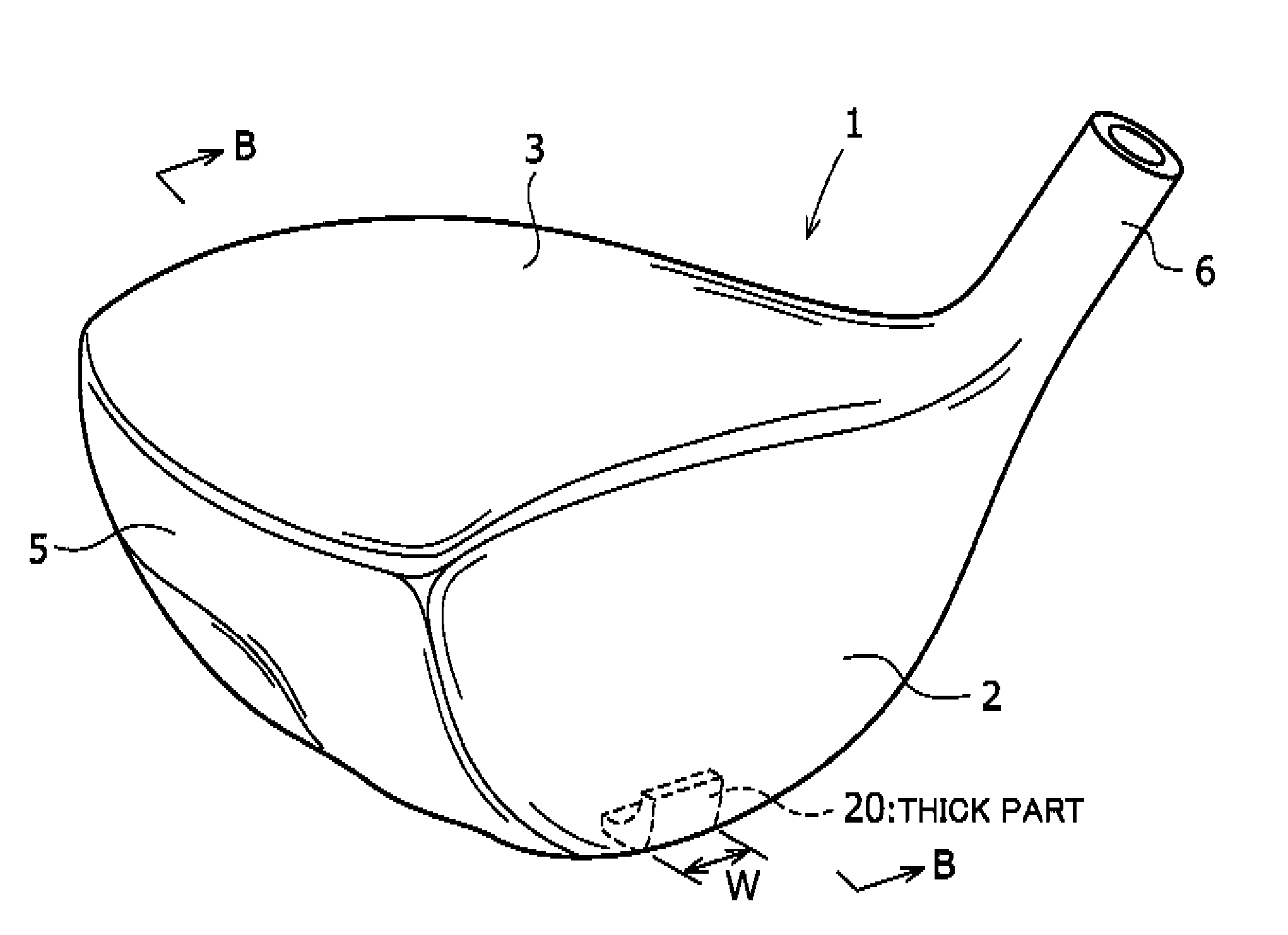
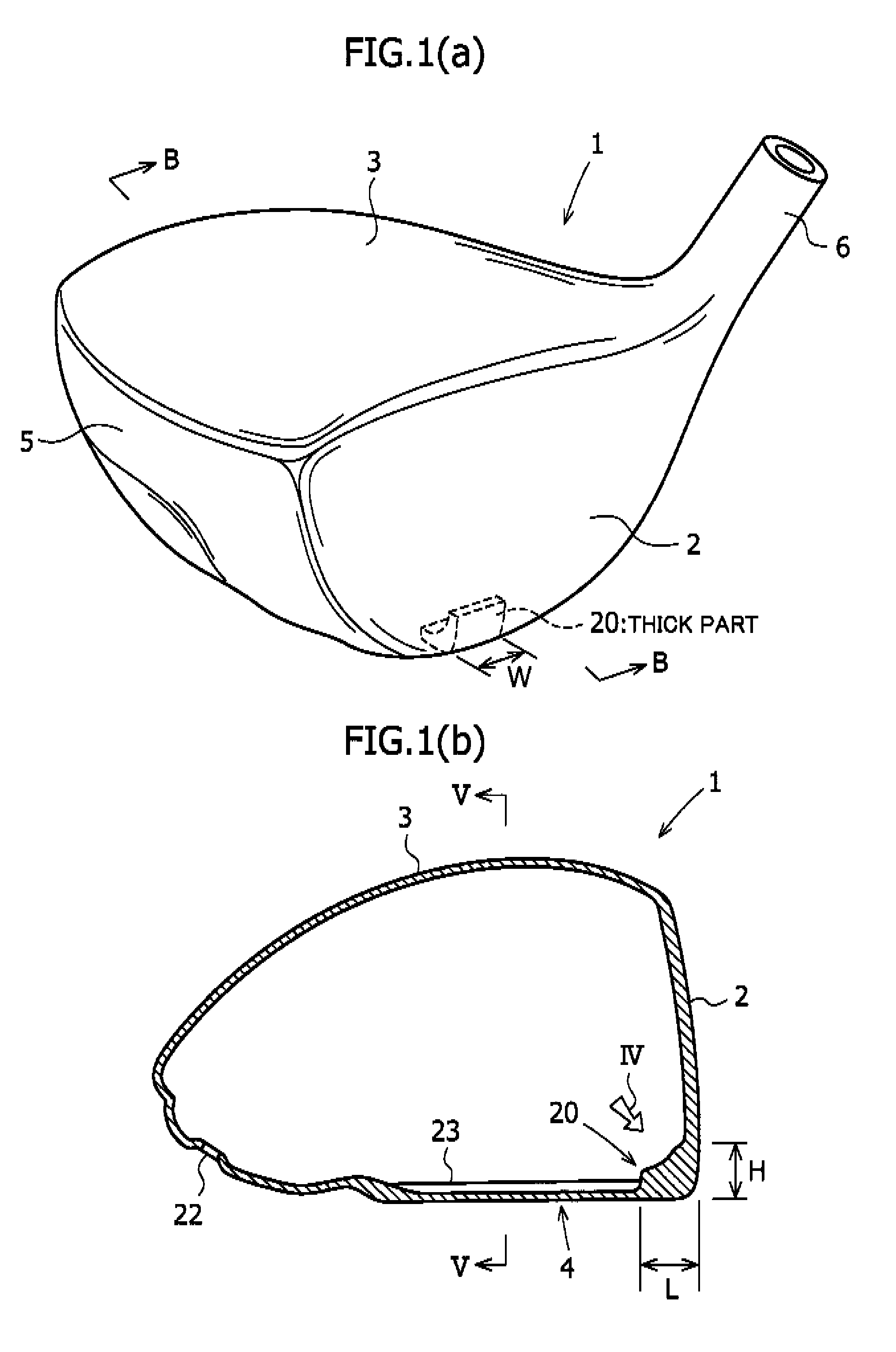
[0048]The thicknesses of the flange parts 16 and 17 of the head body 10 were made 2.5 mm. The thickness of the crown part was made 0.6 mm, that of the side part 0.7 mm, and that of the sole part (excluding the thick part) 0.9 mm. The thickness of the face plate 30 was made 2.8 mm. The dimensions of the thick part 20 were as follows: W=10 mm, H=10 mm, and L=5 mm.

[0049]The initial velocity of ball was measured at the time when a ball was hit by the face center and a ball was hit with the hit position being shifted 10 mm and 15 mm to the toe side at a head speed of 45 m / s using a swing robot manufactured by Miyamae Co., Ltd.

[0050]The measurement results are g...

example 2

[0051]Measurement was made in the same way as Example 1 except that the thickness of face plate 30 was made 2.4 mm. The measurement results are given in Table 1.

example 3

[0052]Measurement was made in the same way as Example 2 except that the width W in the toe-heel direction of the thick part 20 was made 20 mm and the height H was made 20 mm. The measurement results are given in Table 1.


PUM


Abstract

A golf club head 1 has a face part 2, a crown part 3, a sole part 4, a side part 5, and a hosel part 6, which are formed of titanium or a titanium alloy. The golf club head 1 is formed by integrating a head body 10 and a face plate 30 with each other by welding such as laser welding or plasma welding. A thick part 20 is provided only in the central portion in the toe-heel direction of the cross corner portion between the face part 2 and the sole part 4. The width in the toe-heel direction of the thick part 20 is 20 mm or narrower. Therefore, the golf club head in accordance with the present invention can increase a carry on average even if being used by an amateur golfer who is prone to hit a ball by varied hit points across the clubface.

Description

FIELD OF THE INVENTION[0001]The present invention relates to a metallic hollow golf club head and, more particularly, to a large golf club head such as a driver.BACKGROUND OF THE INVENTION[0002]As a wood-type golf club head such as a driver and a fairway wood, a metallic hollow golf club head has been used widely. Generally, the hollow wood-type golf club head comprises a face part for hitting a ball, a crown part constituting the top surface portion of the golf club head, a sole part constituting the bottom surface portion of the golf club head, a side part constituting the side surface portions on the toe side, back side, and heel side of the golf club head, and a hosel part. In this hosel part, a shaft is inserted and fixed by an adhesive or the like.[0003]As a metal forming the hollow golf club head, an aluminum alloy, stainless steel, or titanium alloy has been used, and especially titanium alloy has been used widely in recent years.[0004]Japanese Unexamined Patent Application ...

Claims


Application Information

Patent Timeline
Patent Type & Authority Patents(United States)
IPC IPC(8): A63B53/04A63B102/32
CPCA63B53/0466A63B2053/0412A63B2053/0433A63B2209/00A63B2053/0408A63B2053/0416A63B2053/0454A63B2053/045A63B53/0412A63B53/0408A63B53/0416A63B53/0433A63B53/0454A63B53/045A63B2102/32
Inventor MATSUNAGA, HIDEOKUBOTA, MAKOTOHIRUTA, MASAOMI
Owner BRIDGESTONE SPORTS
Why Eureka
Try Eureka