
Two-stage balancer for multi-lamp backlight

a multi-lamp backlight and balancer technology, which is applied in the direction of instruments, light sources, electrical appliances, etc., can solve the problems of reducing the lifetime of lamps and multi-lamp backlights, and achieve the effects of maintaining uniform brightness of multi-lamp backlights, improving lighting efficiency, and improving current balan

Inactive Publication Date: 2011-05-17
CHICONY POWER TECH CO LTD
View PDF6 Cites 2 Cited by
  • Summary
  • Abstract
  • Description
  • Claims
  • Application Information

AI Technical Summary

Benefits of technology

The present invention provides a two-stage balancer for a multi-lamp backlight that improves current balance and increases lighting efficacy. The balancer includes a first balancing transformer group, a second balancing transformer group, and a lighting unit group. The first balancing transformer group includes multiple first balancing transformers with a primary winding and a secondary winding, which are connected in series in a closed loop. The second balancing transformer group includes multiple second balancing transformers with a primary winding and a secondary winding, which are connected in parallel with the first balancing transformers. The lighting unit group includes multiple lighting units, which are connected to the secondary windings of the balancing transformers. The driving unit provides a driving voltage, which is amplified by the driving transformer to supply a high enough trigger voltage to start up the lighting units. The two-stage balancer provides better current balance and outputs a sinusoid-like driving current to increase lighting efficacy and maintain uniform brightness of the multi-lamp backlight.

Problems solved by technology

Furthermore, the unbalanced current flowed through the lamps will reduce the lifetime of the lamps and the multi-lamp backlight.

Method used


Image

  • Two-stage balancer for multi-lamp backlight
  • Two-stage balancer for multi-lamp backlight
  • Two-stage balancer for multi-lamp backlight

Examples


Embodiment Construction

[0018]In cooperation with attached drawings, the technical contents and detailed description of the present invention are described thereinafter according to a preferable embodiment, being not used to limit its executing scope. Any equivalent variation and modification made according to appended claims is all covered by the claims claimed by the present invention.

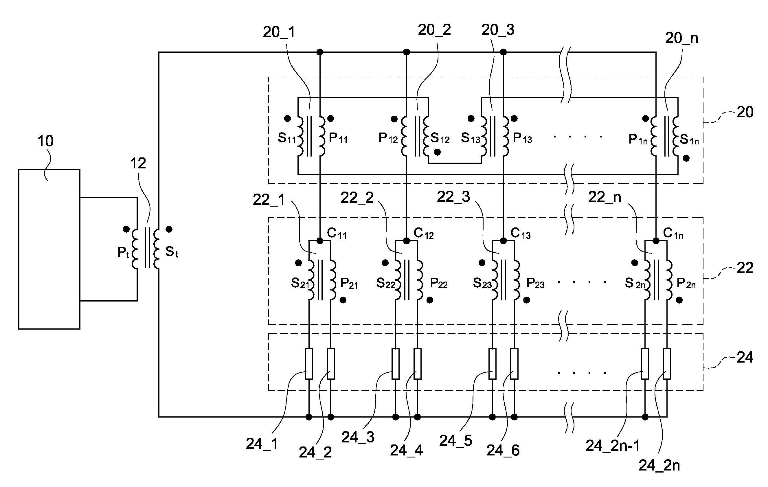
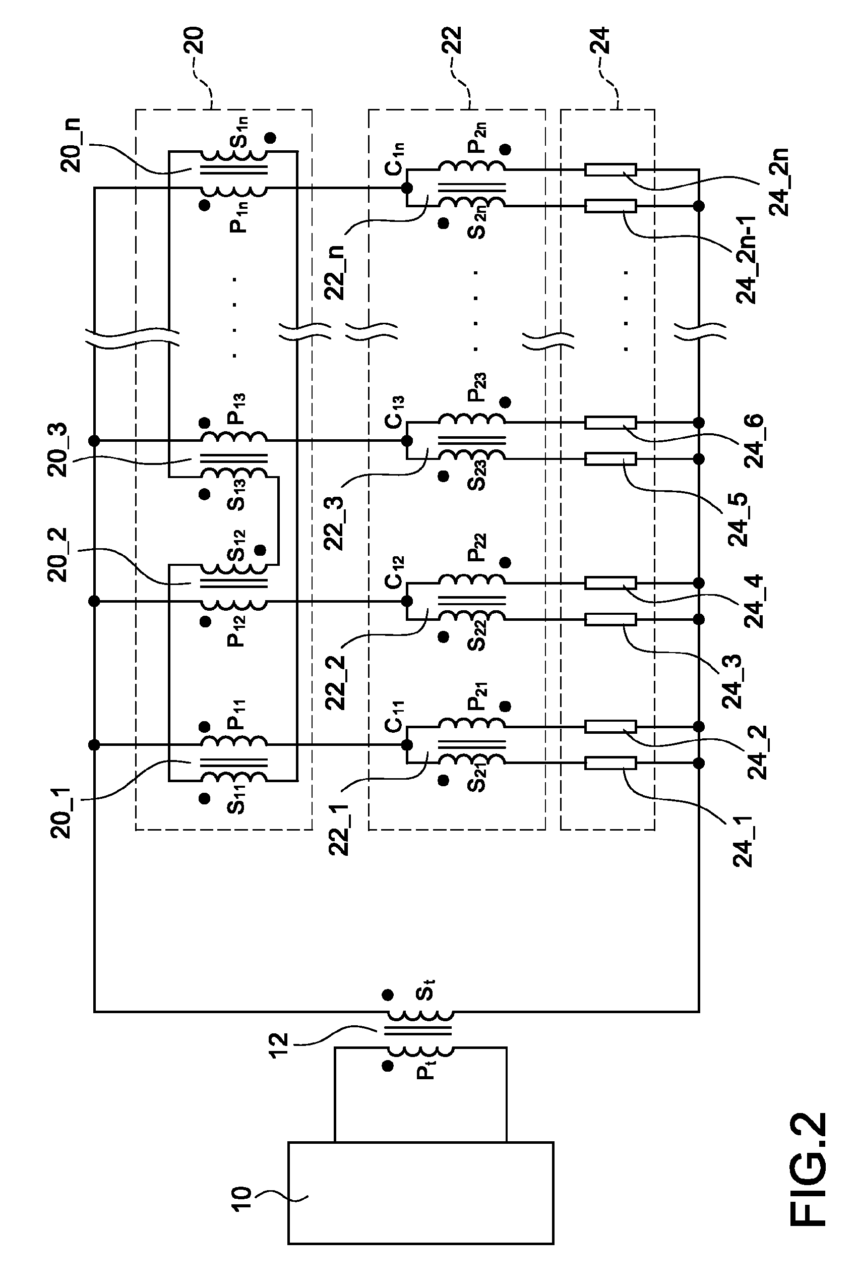
[0019]Reference will now be made to the drawing figures to describe the present invention in detail. Reference is made to FIG. 2 which is a circuit block diagram of a first embodiment of a two-stage balancer for a multi-lamp backlight according to the present invention. The two-stage balancer is electrically connected to a driving unit 10 through a driving transformer 12. The driving unit 10 has a primary winding Pt and a secondary winding St. The two-stage balancer includes a first balancing transformer group 20, a second balancing transformer group 22, and a lighting unit group 24.

[0020]The first balancing transformer gro...


PUM


Abstract

A two-stage balancer for a multi-lamp backlight is electrically connected to a driving unit through a driving transformer. The two-stage balancer includes a plurality of first balancing transformers, second balancing transformers, and lighting units. Each of the first balancing transformers is electrically connected to the corresponding second balancing transformers to form a two-stage structure. In addition, a primary winding and a secondary winding of the second balancing transformer is electrically connected in series to one lighting unit, respectively, to form a circuit loop. Further, each of the circuit loops is electrically connected in parallel. Whereby the two-stage balancer provides much better current balance between the parallel circuit loops, and outputs a sinusoid-like driving current to increase lighting efficacy and further maintain uniform brightness of the multi-lamp backlight.

Description

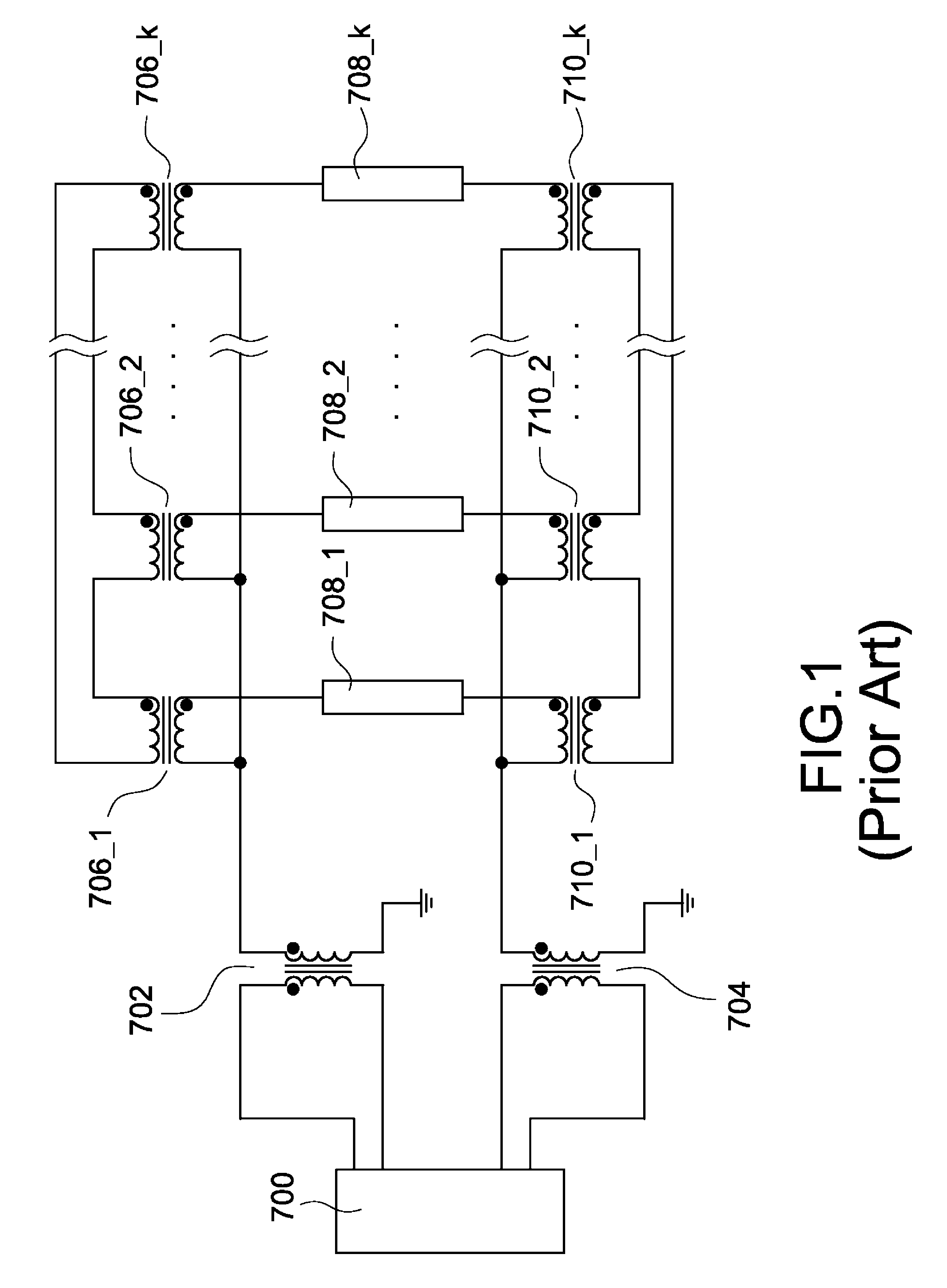
BACKGROUND OF THE INVENTION[0001]1. Field of the Invention[0002]The present invention relates to a two-stage balancer for a multi-lamp backlight, and more particularly to a two-stage balancer for providing much better current balance between parallel circuit loops to maintain uniform brightness of the multi-lamp backlight.[0003]2. Description of Prior Art[0004]In recent years, TFT-LCD has been widely used in different applications with progress of the TFT-LCD display technology, and more particularly in desktop personal computers and multi-media TVs. In order to achieve high-brightness performance for the large-size TFT-LCD applications, the amount of lamps required for a multi-lamp backlight is large. The amount of current flowed through the lamps in parallel is influenced by the impedance between the lamps. Hence, relative brightness of the lamp driven with smaller current is darker; on the contrary, relative brightness of the lamp driven with larger current is lighter to influenc...

Claims


Application Information

Patent Timeline
Patent Type & Authority Patents(United States)
IPC IPC(8): H05B41/24H05B37/00
CPCH05B41/2827
Inventor LEE, SHIH-CHANGHUANG, YI-MINLEE, CHUNG-SHU
Owner CHICONY POWER TECH CO LTD
Learn More