
LED current balancing circuit

A current balance and circuit technology, which is applied in the field of LED current balance circuit, can solve the problems of large circuit power loss, low circuit operation efficiency, complicated circuit, etc., and achieve the effect of current balance

Inactive Publication Date: 2016-08-24
TIAN JIN ATG ELECTRONICS CO LTD
View PDF0 Cites 0 Cited by
  • Summary
  • Abstract
  • Description
  • Claims
  • Application Information

AI Technical Summary

Problems solved by technology

However, the traditional current balance power supply circuit uses a large number of linear voltage regulators and current mirrors to correspond to multiple sets of LED loads, resulting in large power loss and low operating efficiency of the circuit. Relatively more components are used and the circuit is more complicated.

Method used


Image

  • LED current balancing circuit
  • LED current balancing circuit

Examples


Embodiment Construction

[0009] The present invention will be further described below in conjunction with accompanying drawing and embodiment:

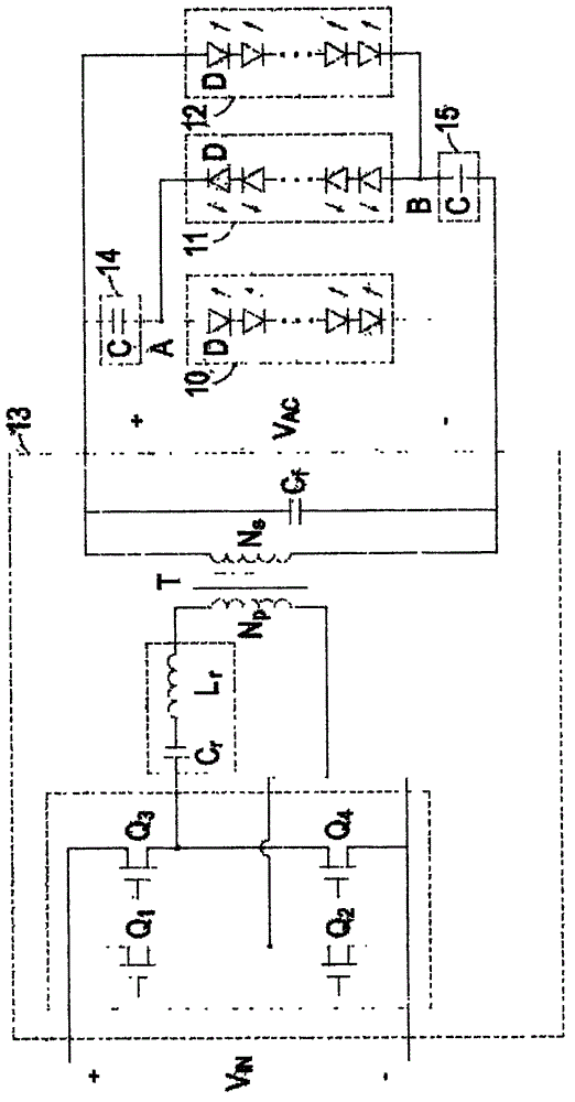
[0010] Such as figure 1 and figure 2 As shown, the LED current balancing circuit includes a first LED assembly 10 , a second LED assembly 11 , a third LED assembly 12 , a first current sharing element 14 and a second current sharing element 15 . The first LED assembly 10 , the second LED assembly 11 and the third LED assembly 12 are provided by an AC power generator 13 with an AC voltage V AC To drive, wherein the first light emitting diode assembly 10 and the second light emitting diode assembly 11 are connected in reverse and in parallel, and the second light emitting diode assembly 11 and the third light emitting diode assembly 12 are also connected in reverse and in parallel, in other words, as figure 2 As shown, the negative end of the first light emitting diode assembly 10 is electrically connected to the negative end of the AC power generator 13, a...


PUM


Abstract

The present invention provides a LED current balancing circuit. The LED current balancing circuit comprises: a first light emitting diode assembly; a second light emitting diode assembly reversely arranged with the first light emitting diode assembly and connected in parallel with a first common connection point; a third light emitting diode assembly reversely arranged with the second light emitting diode assembly and connected in parallel with a second common connection point; an alternating current power supply generator configured to provide the current required to the first power light emitting diode assembly, the second light emitting diode assembly and the third light emitting diode assembly for brightness and connected with the first light emitting diode assembly and the third light emitting diode assembly; a first current sharing element connected between the alternating current power supply generator and the first common connection point to balance the current received by the first and the second light emitting diode assembly; and a second current sharing element connected between the alternating current power supply generator and the second common connection point to balance the current received by the second light emitting diode assembly and the third light emitting diode assembly.

Description

technical field [0001] The invention is a balance circuit, especially an LED current balance circuit. Background technique [0002] Nowadays, LED technology is becoming more and more mature. LED is more and more concerned by people because of its environmental protection and long service life. LED flat panel lights, LED TVs, and LED liquid crystal displays have been more and more accepted and used by people. Light-emitting diodes are DC loads. At present, in the application of multiple light-emitting diodes, because the characteristics of each light-emitting diode are different from each other, the current flowing through each light-emitting diode is different. This not only leads to electronic devices using light-emitting diodes, For example, the uneven luminance of a liquid crystal display panel will greatly reduce the service life of individual light emitting diodes, thereby causing damage to the entire electronic device. At present, advanced light-emitting diodes have s...

Claims


Application Information

Patent Timeline
IPC IPC(8): H05B37/02
Inventor 倪亚西
Owner TIAN JIN ATG ELECTRONICS CO LTD
Learn More