Electric connector

A technology of electrical connectors and power connectors, applied in the direction of connection, two-part connection devices, circuits, etc., can solve problems such as ablation, easily damaged electrical components, and increase impedance, and achieve the effect of current protection

Inactive Publication Date: 2004-07-21
FOXCONN (KUNSHAN) COMPUTER CONNECTOR CO LTD +1
View PDF2 Cites 0 Cited by
  • Summary
  • Abstract
  • Description
  • Claims
  • Application Information

AI Technical Summary

Problems solved by technology

[0004] However, when the above-mentioned electrical connector is plugged and unplugged, the load circuit is turned on and off in an instant, and the instantaneous high voltage generated by the inherent capacitance and inductance in the load circuit will be in the electrical connector. When the switch is connected to the discharge and sparks, the contact contacts of the electrical connector are ablated, the impedance is increased, and the product efficiency is reduced; at the same time, the high-voltage pulse generated due to the instantaneous on and off of the current is also easy to damage the electrical components in the circuit

Method used


Image

  • Electric connector
  • Electric connector
  • Electric connector

Examples


Embodiment Construction

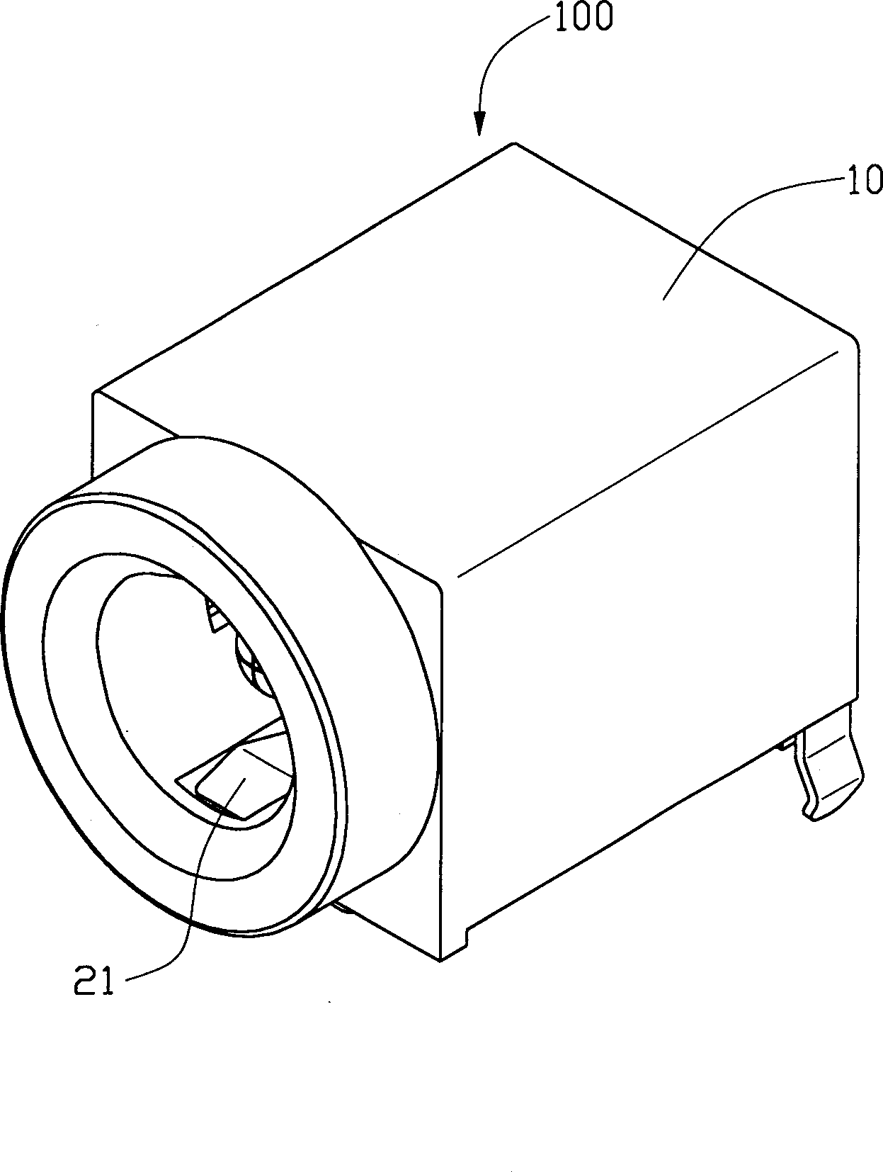
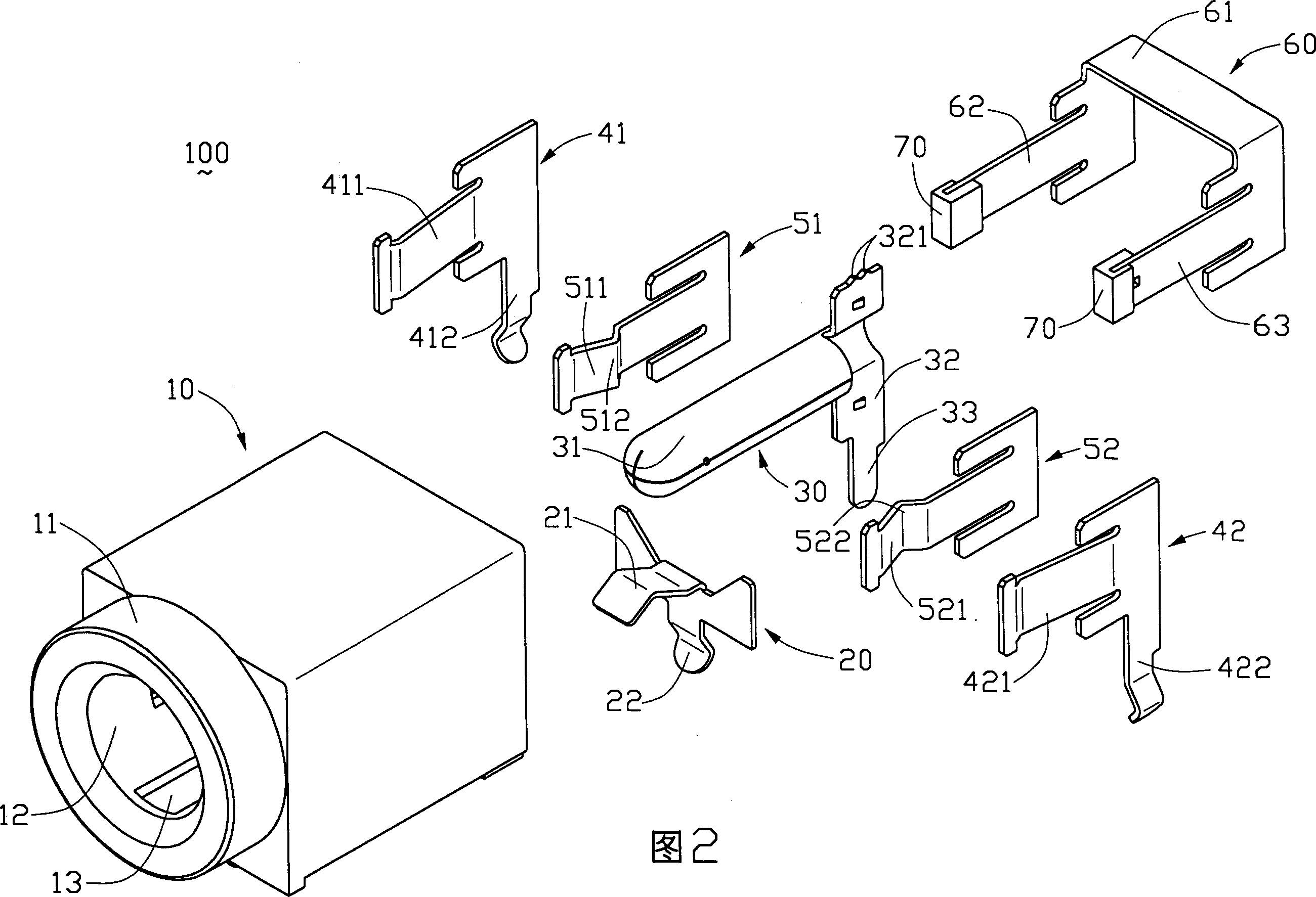
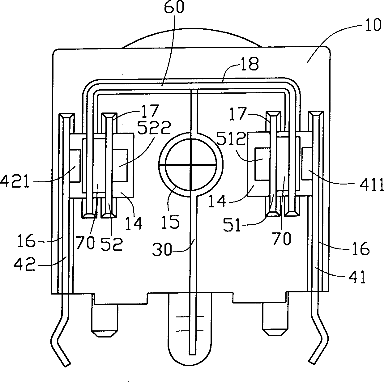
[0020] see Figure 1 to Figure 3 The electrical connector 100 of the present invention includes an insulating body 10 and a grounding terminal 20 , a central terminal 30 , conductive terminals 41 , 42 , switch terminals 51 , 52 and a connecting body 60 installed in the insulating body 10 .

[0021] Please also refer to Figure 4 The insulating body 10 is provided with a cylindrical docking portion 11 and an inner cavity at the front end, and the cavity includes a circular inner cavity hole 12 along the axial direction of the insulating body 10 and rectangular side cavity holes 14 on both sides of the inner cavity hole 12 ; The cavity hole 12 is used to accommodate the docking connector, and is provided with a mounting portion 13 at its bottom and the inner surface near the front opening (that is, the bottom end of the docking portion 12), and the mounting portion 13 consists of a rectangular through hole and a Vertical slots; the side cavity holes 14 are used to accommodate t...


PUM


Abstract

The electric connector with the function of resisting spark-over includes an insulator and a central terminal, several conducting terminals, several switch terminals and a connector which are placed in the insualtor. The front end of every switch terminal possesses pick-up portion, and the pick-up portions of all switch terminals are properly spaced on the axial direction of electric connector, and the central terminal is electrically connected with connecting body, and between the switch terminal and connector there is an insulating block for separating them. When the butt-joint connected is inserted, the butt-joint connector is electrically connected with central terminal fistly, then all the switch terminals are started successively, and the connector and the conducting terminals are contacted one after another so as to implement electric connection.

Description

【Technical field】 [0001] The invention relates to an electrical connector, in particular to an electrical connector with the function of preventing ignition and balancing circuit current. 【Background technique】 [0002] It is a well-known technology in the industry that various electronic products are connected to a DC power supply by using an electrical connector. Generally speaking, this type of electrical connector includes a central terminal and surrounding elastic blade terminals. In practical applications, a load is connected between the central terminal and the blade terminals. For example, U.S. Patent No. 5,927,999 discloses an electrical connector with three movable contact terminals around its center terminal. When the butt connector is inserted, three points can contact the butt connector at the same time, which can solve the phenomenon of insufficient holding force when there is only one point of contact, and at the same time allow a larger current flow. [000...

Claims


Application Information

Patent Timeline
Patent Type & Authority Patents(China)
IPC IPC(8): H01R13/71H01R24/38
Inventor 牟之权朱自强
Owner FOXCONN (KUNSHAN) COMPUTER CONNECTOR CO LTD
Why Eureka
Try Eureka