Fluid reservoir for penile implant devices

a penile implant and fluid reservoir technology, applied in the field of surgical implant devices, can solve the problems of inflation of the prosthesis, affecting the normal erection of the erection,

Active Publication Date: 2011-05-24
BOSTON SCI SCIMED INC
View PDF173 Cites 19 Cited by
  • Summary
  • Abstract
  • Description
  • Claims
  • Application Information

AI Technical Summary

Benefits of technology

[0005]The invention relates to devices and methods that overcome certain shortcomings of the prior fluid reservoirs fro penile implant devices. In particular, the invention provides fluid reservoirs with a design that eliminates the requirement for placement below the puborectalis muscle, anterior to the transversalis fascia. Thus, the invention provides fluid reservoirs having sufficiently small depth that enables them to be implanted submuscularly in the lower abdomen where they will be virtually undetectable from outside the patient's body. In particular, the reservoir length and width are designed and / or chose so that the reservoir can fit in the patient lateral to the midline of the lower abdomen. This location can be relatively easy for the surgeon to reach during implantation of the device, and provides for a less intrusive device implantation than the surgery required for some other reservoirs.

Problems solved by technology

This results in the inflation of the prostheses and produces rigidity for a normal erection.
This approach can be relatively difficult, particularly for less experienced surgeons.

Method used


Image

  • Fluid reservoir for penile implant devices
  • Fluid reservoir for penile implant devices
  • Fluid reservoir for penile implant devices

Examples


Embodiment Construction

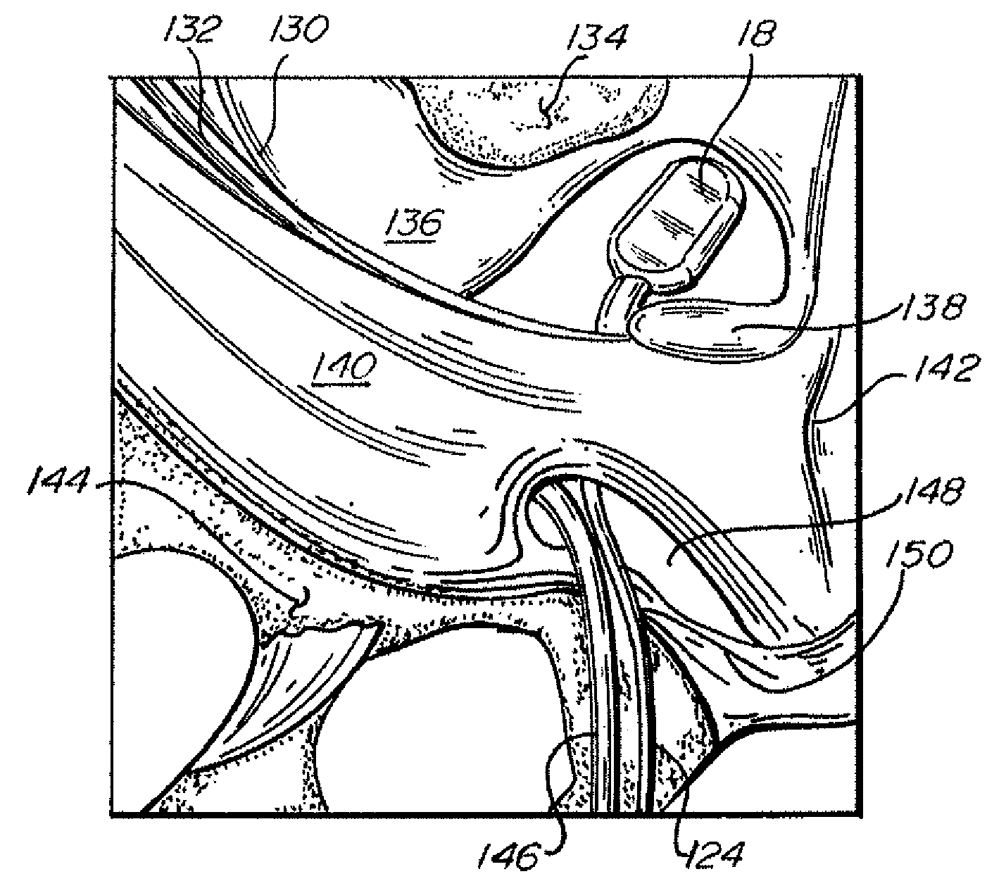
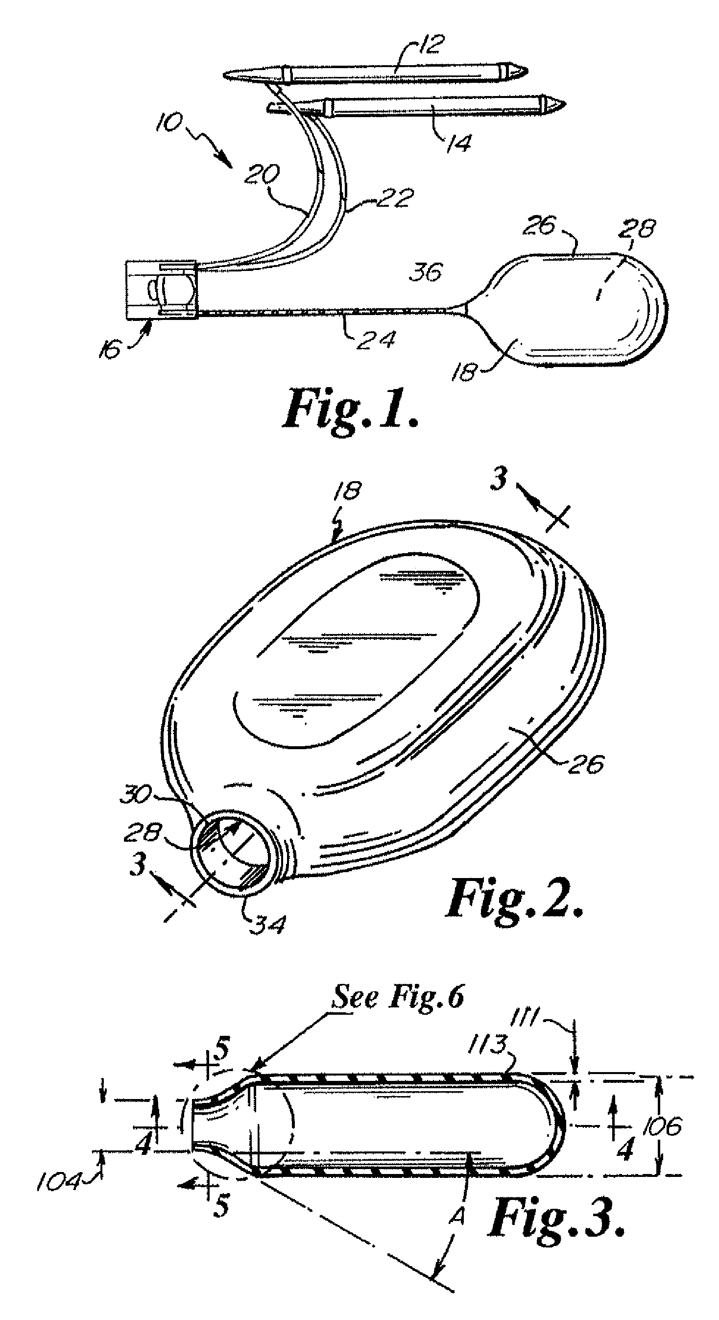
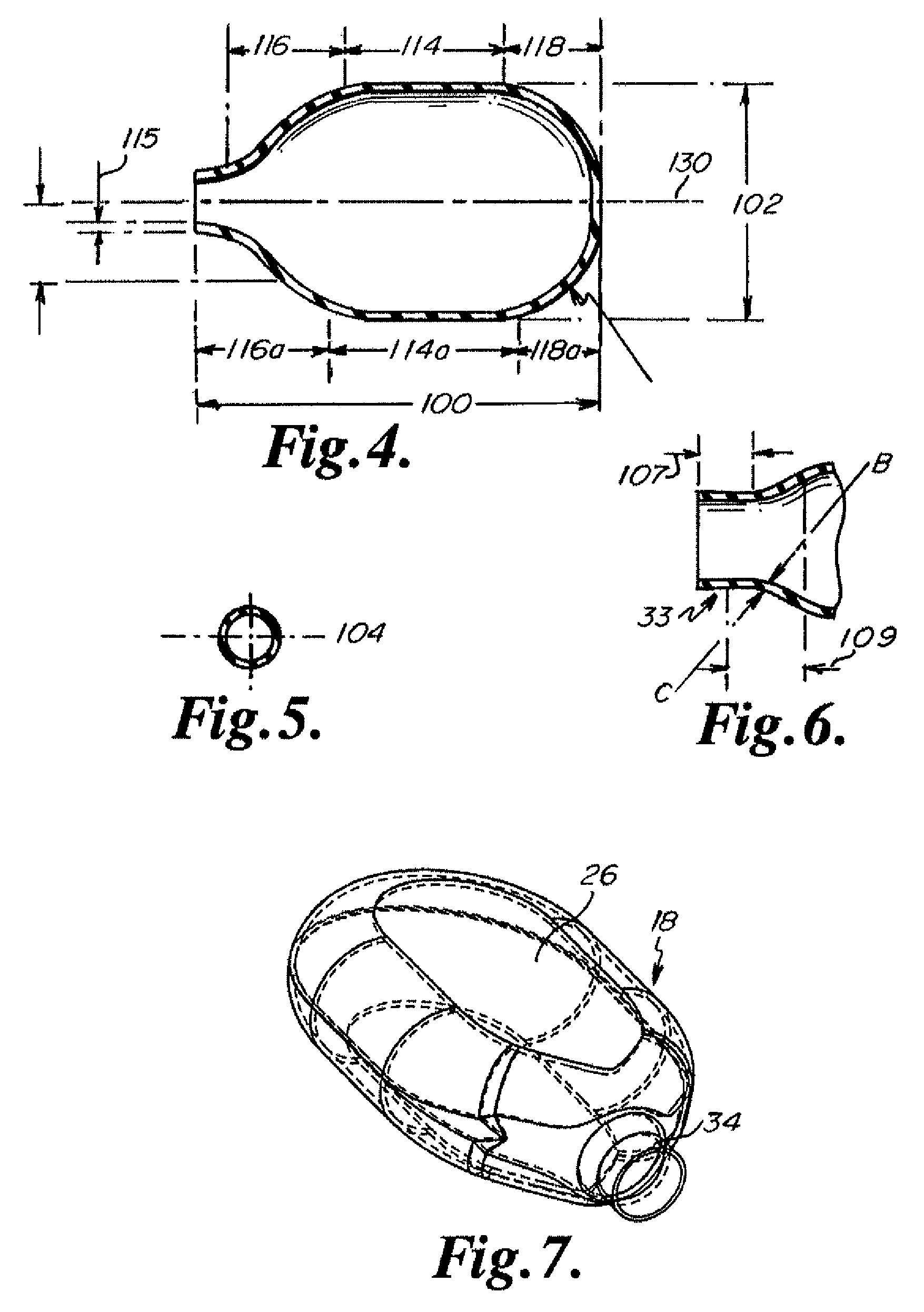
[0025]Referring now to the Figures, wherein the components are labeled with like numerals throughout the several Figures, and initially to FIG. 1, the preferred configuration of a surgically implantable penile prosthesis device 10 having a three-piece design is illustrated. As shown, device 10 generally includes first and second inflatable penile cylinders 12 and 14, respectively, a pump 16, and a reservoir 18 in accordance with the invention. First penile cylinder 12 is fluidly coupled to pump 16 by a tube 20 and second penile cylinder 14 is fluidly coupled to pump 16 by a tube 22. Pump 126 is fluidly coupled to reservoir 18 by tube 24. When device 10 is implanted into a patient, cylinders 12 and 14 are surgically located in the corpus cavernosa regions of a penis and pump 16 is located within the scrotum of a patient, while reservoir 18 is located within the abdominal area of the patient. In user, the patient can activate pump 16 in some manner (e.g., squeezing the body or other p...


PUM


Abstract

The invention is directed to a medical device, particularly a penile prosthesis, that includes an implantable element and a reservoir. The implantable element is configured to be implanted within the pelvic region of a patient and is designed to be capable of inflation and deflation via fluid transfer to and from the element. The reservoir is coupled to the implantable element. The fluid is drawn from the reservoir for inflation of the implantable element and returned to the reservoir for the deflation. The reservoir is approximately one inch or less in depth. The minimal depth enables the fluid reservoir to be placed in front of the puborectalis muscle and behind the abdominal fascia without being seen on an external view of the patient.

Description

CLAIM TO PRIORITY[0001]The present application claims priority to U.S. provisional patent application 60 / 669,427, filed Apr. 8, 2005 and entitled “Fluid Reservoirs for Penile Implant Devices” and to U.S. provisional patent application 60 / 669,673, filed Apr. 8, 2005 and entitled “Fluid Reservoirs for Penile Implant Devices”. The noted provisional patent applications are hereby incorporated by reference.FIELD OF THE INVENTION[0002]The present invention relates generally to surgical implant devices for containing fluid. More particularly, the present invention relates to fluid reservoirs for use with penile implant devices and related methods for implantation of such reservoirs.BACKGROUND OF THE INVENTION[0003]One common treatment for erectile dysfunction includes the use of a penile implant device. A particular type of penile implant device, commonly known as a three-piece device, includes a pair of inflatable cylindrical prostheses that are implanted into the corpus cavernosae of the...

Claims


Application Information

Patent Timeline
Patent Type & Authority Patents(United States)
IPC IPC(8): A61F2/02
CPCA61F2/26
Inventor GEORGE, STEPHANIE A.ALBRECHT, JON D.RYKHUS, ROBERT L.WILSON, STEVEN K.
Owner BOSTON SCI SCIMED INC
Why Eureka
Try Eureka