Locking polyaxial ball and socket fastener

a polyaxial ball and socket technology, applied in the field of ball and socket fasteners, can solve the problems of large inventory, inability to determine the structure of the bone, and the anchoring screw may still require angular insertion, so as to reduce the amount of inventory required

Active Publication Date: 2011-05-24
ORTHO INNOVATIONS
View PDF442 Cites 139 Cited by
  • Summary
  • Abstract
  • Description
  • Claims
  • Application Information

AI Technical Summary

Benefits of technology

[0040]This construction facilitates the receipt of the spherical connector into the bottom of the connector member, eliminating the requirement of inserting the screw and spherical connector through the top opening of the connector member. This construction also allows for the use of bone anchors that will not fit through the top opening of the connector member. In addition, the use of the dual retainer rings allows for the coupling of an anchor screw to a connector member during surgery, without the aid of tools. In this manner, during surgery a surgeon can determine the most advantageous bone screw, hook or other type of bone connection to match the most advantageous connecting assembly. The bone connector is then coupled to the connector assembly by inserting or snapping the spherical connector into the socket of the connecting assembly. In operation, the spherical connector is pushed past the lower retainer ring whereby the ring snaps past the largest diameter of the connector to prohibit removal of the connector while still allowing polyaxial movement between the spherical ball and the connector member. Because of the flexibility and resilience of the split retention ring, the mating parts do not require fine tolerances and are economical to manufacture. The system is modular, employing a collection of anchoring assemblies that are linked, via various connectors, to strategically-arranged stabilizing rods.
[0044]Another objective of the invention is to disclose the use of a lockable polyaxial ball and socket system that is capable of securing various anchors to various connector members so as to reduce the amount of inventory required to meet a particular installation.
[0045]It is another objective of the present invention to provide a polyaxial bone screw assembly for a spinal fixation system that permits component adjustment during installation, thereby enabling satisfactory correction of a wide variety of spinal deformities.
[0046]It is an additional objective of the present invention to provide a bone screw assembly that includes a split ring locking mechanism that is simple, strong and reliable.
[0048]It is yet another objective of the present invention to provide a spinal fixation system that require minimum tools for installing of an anchor and securing element.

Problems solved by technology

Known spinal implant systems often correct one set of problems only to create new ones.
A problem with the current technology is that bone structure cannot be determined until the patient's bone is exposed.
This problem requires a large inventory of various sized implants to be on hand during every surgery.
Even if an implant combination is predicted, the anchoring screw may still require angular insertion due to muscle structure or nerve locations.
Any movement of muscle and other tissue increases the difficulty of the operation and can be a major trauma to the patient.
Still yet, bone condition may require oversize threads to achieve a suitable purchase to the bone.
A problem with the screw is the need for the locking pin and the inability of the base screw to accommodate a threaded extension bolt.

Method used


Image

  • Locking polyaxial ball and socket fastener
  • Locking polyaxial ball and socket fastener
  • Locking polyaxial ball and socket fastener

Examples


Embodiment Construction

[0095]While the present invention is susceptible of embodiment in various forms, there is shown in the drawings and will hereinafter be described a presently preferred embodiment with the understanding that the present disclosure is to be considered an exemplification of the invention and is not intended to limit the invention to the specific embodiments illustrated.

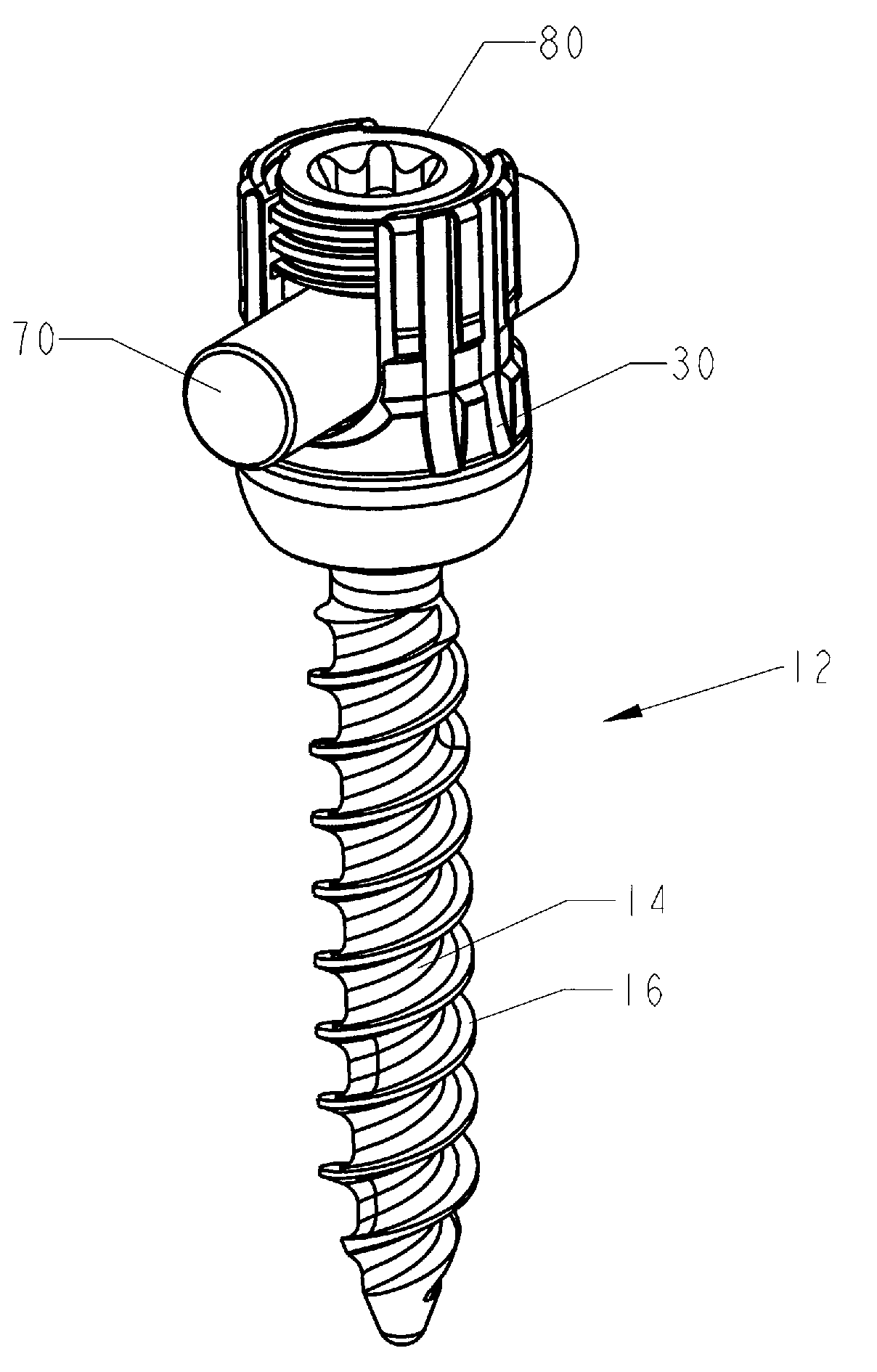
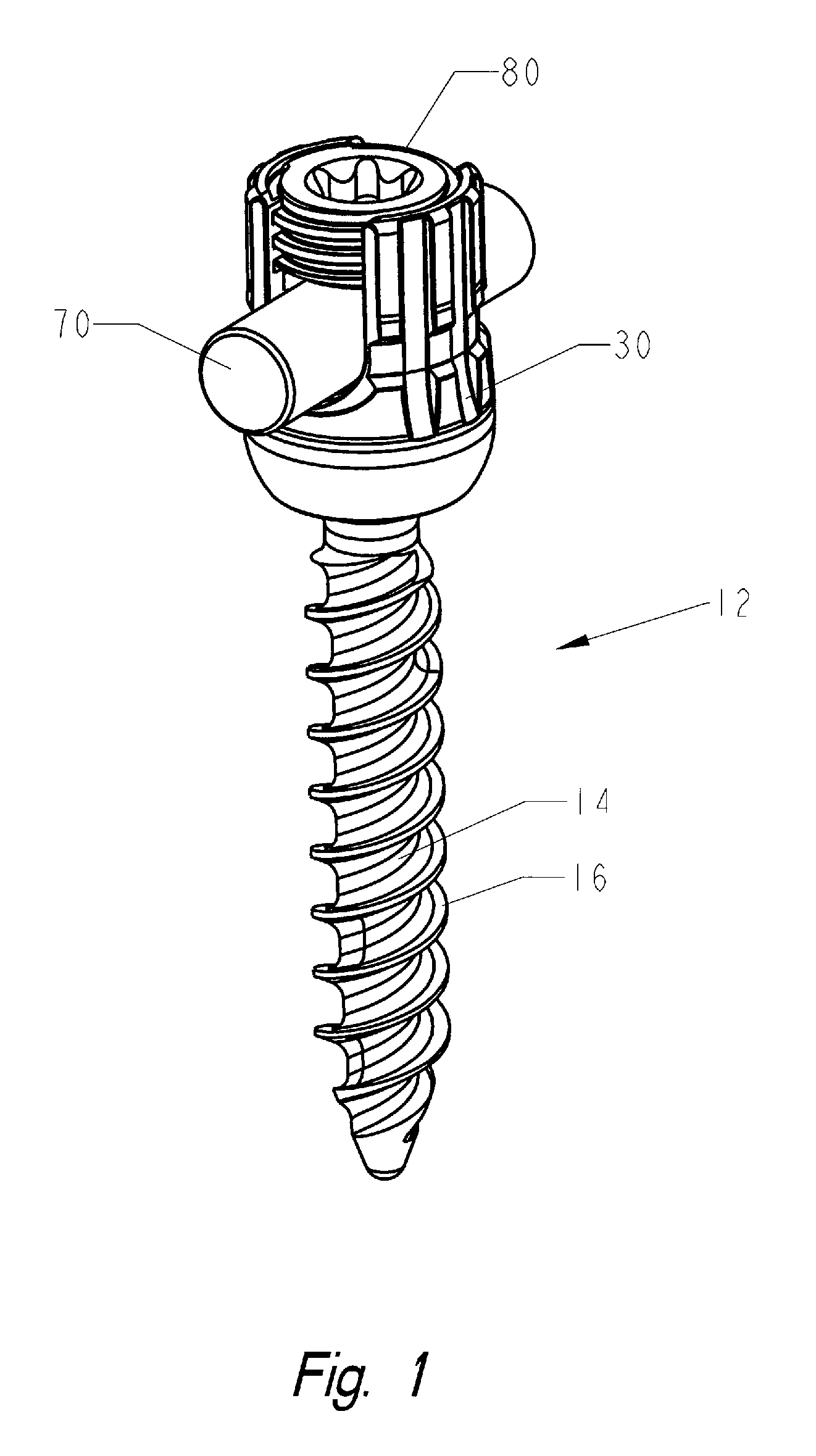
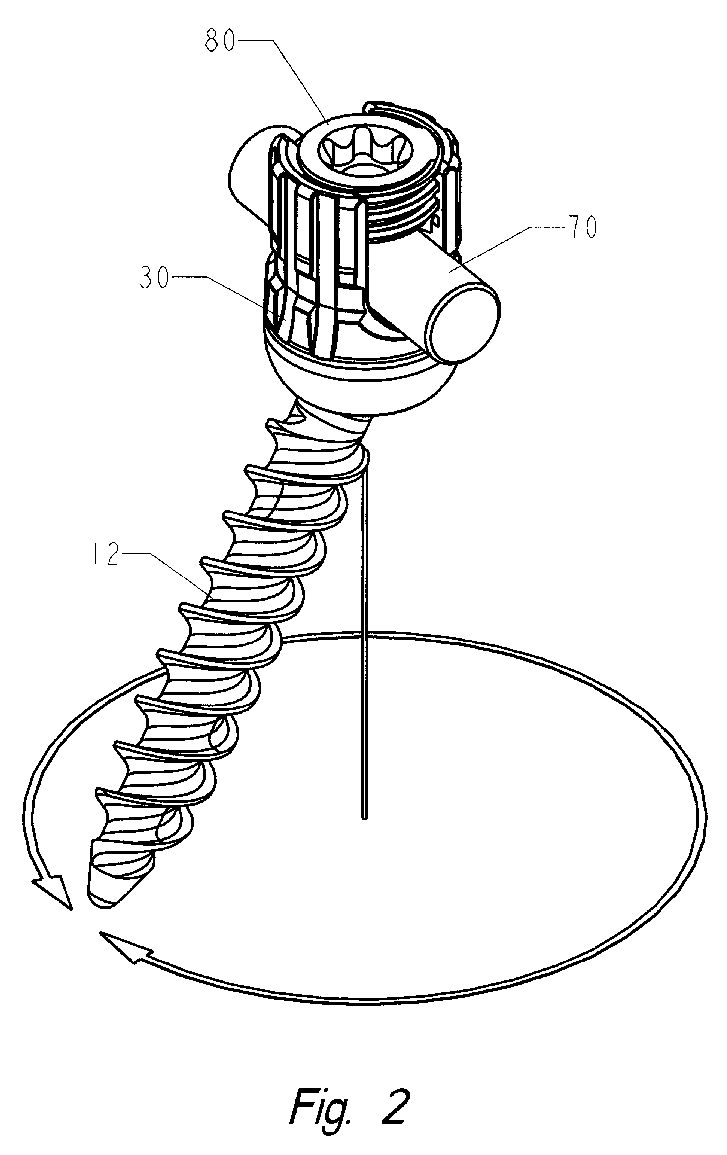
[0096]Referring generally to the Figures, disclosed is an exemplary embodiment of the locking polyaxial ball and socket fastening system adapted for use in a spinal fixation system. The fastening system includes a spherical ball secured or formed integrally with a bone anchor and connecting assembly that includes a snap-in type receptacle (38) for the spherical ball to form a polyaxial joint. The connector assembly also includes a receiver that may be used in conjunction with a connecting rod member for securing at least two bone anchors together.

[0097]Referring to FIGS. 1-4 and 19, the bone anchor of the preferred embod...


PUM


Abstract

A polyaxial ball and socket joint that can be locked into a fixed position. The fastening system consists of the polyaxial ball and socket joint used in conjunction with a bone screw having threads on one end for use in anchoring to the spine and a spherical connector on the other end operating as a pivot point about which a connecting assembly moves in a polyaxial fashion. A substantially U-shaped connecting assembly has a lower receptacle that operates as a socket for housing an upper retainer ring and a lower split retaining ring. The socket is receptive to the spherical connector which is inserted through the lower split retainer ring causing a momentary displacement thereof which allows for the positioning of the spherical connector between the upper and lower retainer rings.

Description

CROSS REFERENCE TO RELATED APPLICATIONS[0001]This application claims the benefit of the filing date of U.S. Provisional Patent Application No. 61 / 114,515 filed on Nov. 14, 2008, the contents of which are herein incorporated by reference.FIELD OF THE INVENTION[0002]This invention is directed to the field of ball and socket fasteners, and in particular to a polyaxial ball and socket fastener adapted for use as a spinal implant.BACKGROUND OF THE INVENTION[0003]There are numerous ball and socket fasteners, however, when the application is applied to a particular product, the ball and socket must meet minimum specifications in order to be effective. For instance, in the field of spinal pathologies, the development of spinal fixation devices represents a major medical breakthrough. Surgically implanted fixation systems are commonly used to correct a variety of back structure problems, including those which occur as a result of trauma or improper development during growth. A commonly appli...

Claims


Application Information

Patent Timeline
Patent Type & Authority Patents(United States)
IPC IPC(8): A61B17/70
CPCA61B17/7037A61B17/7038A61B17/7035A61B17/56A61B17/70A61B17/7032A61B17/86A61F2/44
Inventor HAMMILL, SR., JOHN E.DOUBLER, ROBERT L.
Owner ORTHO INNOVATIONS
Why Eureka
Try Eureka