Posterior-medial facet support assembly

a facet support and anterior-medial technology, applied in the field of posterior-medial facet support assembly, can solve the problems of affecting the ability to stabilize the spine, and achieve the effect of stabilizing the spinal segment and preventing excessive motion

Active Publication Date: 2011-05-24
SPINE21 LTD
View PDF2 Cites 9 Cited by
  • Summary
  • Abstract
  • Description
  • Claims
  • Application Information

AI Technical Summary

Benefits of technology

[0005]One of the chief functions of the native facets is to stabilize the spinal segment and prevent excessive motion in the different directions. Each vertebra has two bilateral superior processes that create two bilateral joints with the two bilateral inferior processes of the vertebra above and two bilateral inferior processes that create two joints with the bilateral superior processes of the vertebra bellow. The two bilateral inferior processes of each vertebra are supported by the lamina and the pars to have the proper mechanical strength.

Problems solved by technology

After a decompression procedure, a significant amount of the facet's bony support may be removed and thus its ability to stabilize the spine is compromised.

Method used


Image

  • Posterior-medial facet support assembly
  • Posterior-medial facet support assembly
  • Posterior-medial facet support assembly

Examples


Embodiment Construction

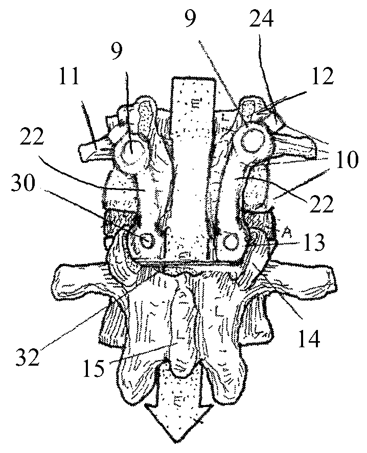
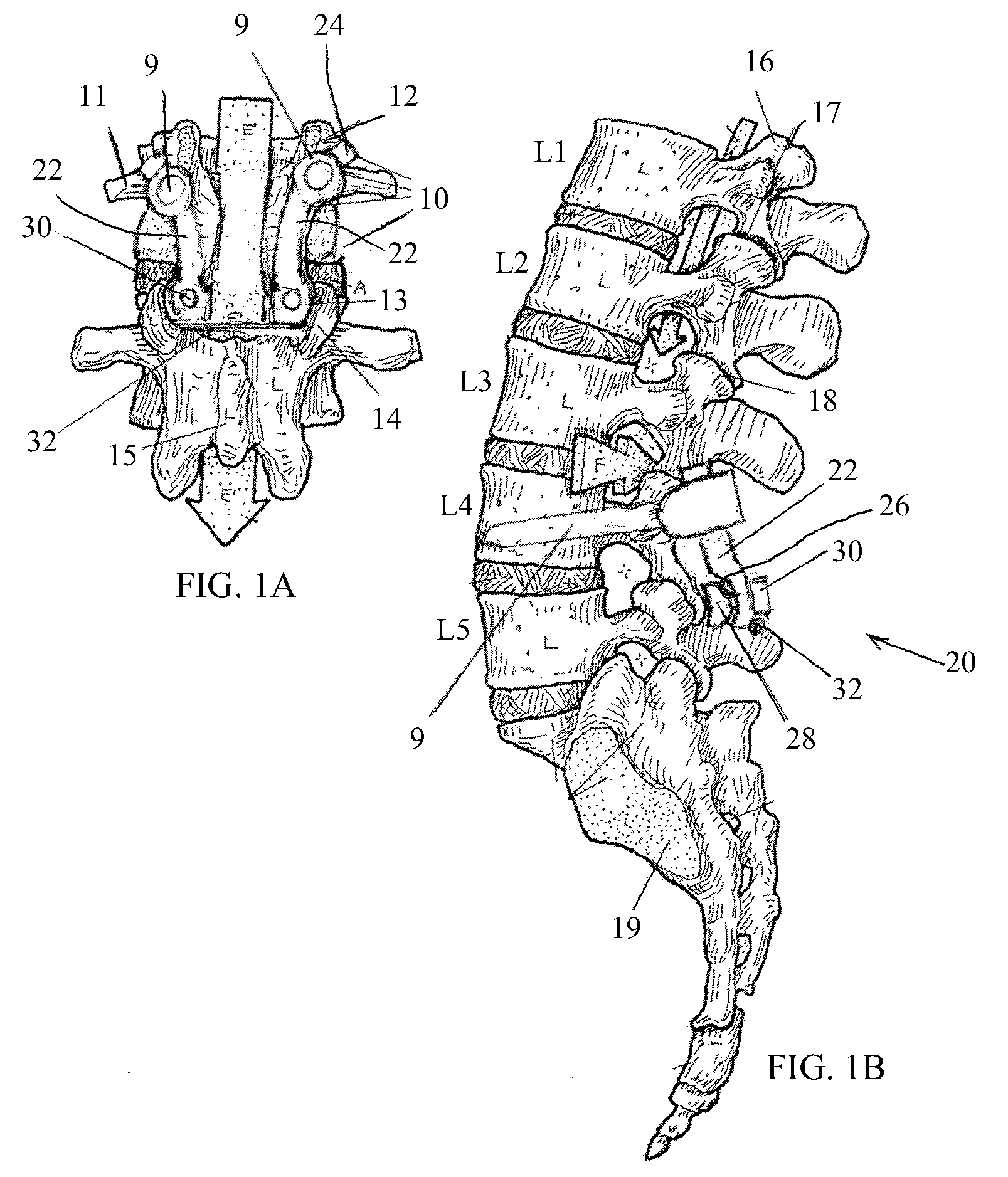
[0018]FIG. 1A illustrates the area of two adjacent lumbar vertebrae, showing the body 10 of the vertebra, the transverse process 11, superior articular process 12, and inferior articular process 13 of the superior vertebra, and the superior articular process 14 and spinous process 15 of the inferior vertebra. FIG. 1B illustrates the area of the L1-L5 vertebrae, showing the L1 superior articular process 16, L1 inferior articular process 17, a facet joint 18 between L2 and L3, and the auricular surface 19 for the iliac bone.

[0019]As seen in FIG. 1B, a laminectomy decompression has been performed on L4, wherein the spinous process and the lamina have been removed. Two polyaxial pedicle screws 9 have been screwed into the pedicles of L4.

[0020]In accordance with an embodiment of the present invention, as illustrated in FIGS. 1A-1B, a posterior-medial facet support assembly 20 is provided for helping support the facets. The facet support assembly 20 includes at least one rod 22, whose upp...


PUM


Abstract

A facet support assembly including at least one rod including an upper portion rigidly fixed to a spinal fastener, and a lower portion configured to support an inferior articular process, wherein when the spinal fastener is secured to a pedicle of a lumbar vertebra, the lower portion of the at least one rod abuts against and supports the inferior articular process of the same lumbar vertebra.

Description

FIELD OF THE INVENTION[0001]The present invention is generally related to apparatus and methods for spinal prostheses or implants, and particularly to a posterior-medial facet support assembly.BACKGROUND OF THE INVENTION[0002]Through the course of life, disease or injury, the spinal canal, the laminae, or facets of one or more vertebral bodies can degenerate or become damaged, such that the spinal cord and / or nerve roots become compressed. This can result in an undesired anatomy, loss of mobility, and pain or discomfort. For example, spinal stenosis, as well as spondylosis, spondylolisthesis, osteoarthritis and other degenerative phenomena may cause back and leg pain. Such phenomena may be caused by a narrowing of the spinal canal by a variety of causes that result in the pinching of the spinal cord and / or nerves in the spine.[0003]Decompression and fusion of two or more adjacent vertebrae are common options for treating these problems. However, it is known that fusion tends to caus...

Claims


Application Information

Patent Timeline
Patent Type & Authority Patents(United States)
IPC IPC(8): A61B17/70
CPCA61B17/7064
Inventor ARNIN, URI
Owner SPINE21 LTD
Why Eureka
Try Eureka