Signaling completion of a message transfer from an origin compute node to a target compute node

a message transfer and target technology, applied in the field of data processing, can solve the problems of limiting the potential speed of serial processors, affecting the performance of serial processors, and affecting the performance of serial processors, and affecting the ability of serial processors to achieve the effect of a single fast processor

Inactive Publication Date: 2011-05-24
INT BUSINESS MASCH CORP
View PDF31 Cites 32 Cited by
  • Summary
  • Abstract
  • Description
  • Claims
  • Application Information

AI Technical Summary

Problems solved by technology

Since that time, computer systems have evolved into extremely complicated devices.
It is far more difficult to construct a computer with a single fast processor than one with many slow processors with the same throughput.
There are also certain theoretical limits to the potential speed of serial processors.
After that point adding more processors does not yield any more throughput but only increases the overhead and cost.
Shared memory processing needs additional locking for the data and imposes the overhead of additional processor and bus cycles and also serializes some portion of the algorithm.
Message passing processing uses high-speed data communications networks and message buffers, but this communication adds transfer overhead on the data communications networks as well as additional memory need for message buffers and latency in the data communications among nodes.
A torus network lends itself to point to point operations, but a tree network typically is inefficient in point to point communication.
The drawback to current methods used by the DMA engine to notify the application that the transfer is complete is that the DMA engine must typically wait for an acknowledgement message from the compute node receiving the transfer before notifying the application that the transfer is complete.
Waiting for an acknowledgement message from the compute node that received the transfer often introduces additional latency penalties when processing the application.

Method used


Image

  • Signaling completion of a message transfer from an origin compute node to a target compute node
  • Signaling completion of a message transfer from an origin compute node to a target compute node
  • Signaling completion of a message transfer from an origin compute node to a target compute node

Examples


Embodiment Construction

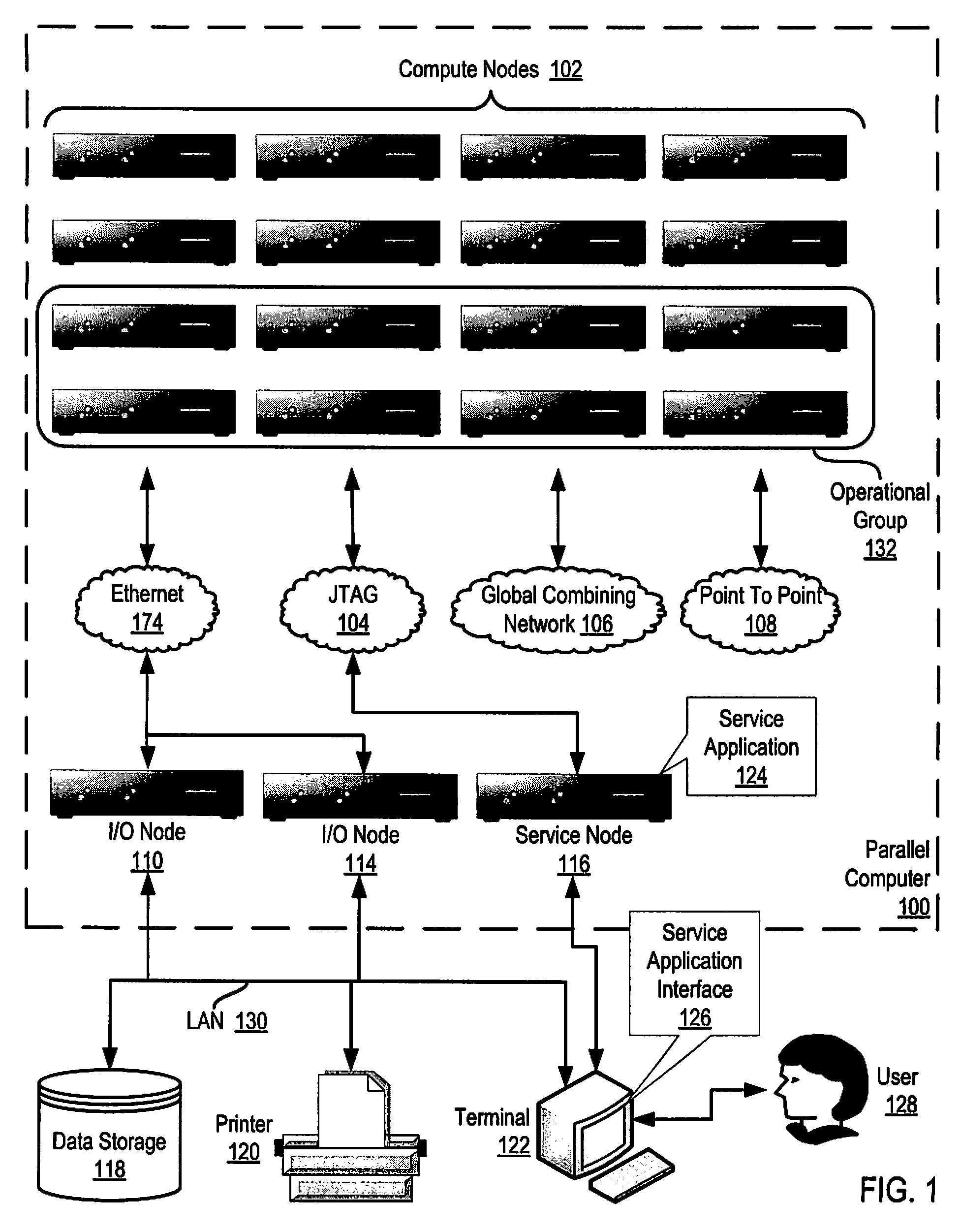
[0024]Exemplary methods, apparatus, and computer program products for signaling completion of a message transfer from an origin compute node to a target compute node according to embodiments of the present invention are described with reference to the accompanying drawings, beginning with FIG. 1. FIG. 1 illustrates an exemplary system for signaling completion of a message transfer from an origin compute node to a target compute node according to embodiments of the present invention. The system of FIG. 1 includes a parallel computer (100), non-volatile memory for the computer in the form of data storage device (118), an output device for the computer in the form of printer (120), and an input / output device for the computer in the form of computer terminal (122). Parallel computer (100) in the example of FIG. 1 includes a plurality of compute nodes (102).

[0025]The compute nodes (102) are coupled for data communications by several independent data communications networks including a hi...


PUM


Abstract

Signaling completion of a message transfer from an origin node to a target node includes: sending, by an origin DMA engine, an RTS message, the RTS message specifying an application message for transfer to the target node from the origin node; receiving, by the origin DMA engine, a remote get message containing a data descriptor for the message and a completion notification descriptor, the completion notification descriptor specifying a local direct put transfer operation for transferring data locally on the origin node; inserting, by the origin DMA engine in an injection FIFO buffer, the data descriptor followed by the completion notification descriptor; transferring, by the origin DMA engine to the target node, the message in dependence upon the data descriptor; and notifying, by the origin DMA engine, the application that transfer of the message is complete in dependence upon the completion notification descriptor.

Description

STATEMENT REGARDING FEDERALLY SPONSORED RESEARCH OR DEVELOPMENT[0001]This invention was made with Government support under Contract No. B554331 awarded by the Department of Energy. The Government has certain rights in this invention.BACKGROUND OF THE INVENTION[0002]1. Field of the Invention[0003]The field of the invention is data processing, or, more specifically, methods, apparatus, and products for signaling completion of a message transfer from an origin compute node to a target compute node.[0004]2. Description of Related Art[0005]The development of the EDVAC computer system of 1948 is often cited as the beginning of the computer era. Since that time, computer systems have evolved into extremely complicated devices. Today's computers are much more sophisticated than early systems such as the EDVAC. Computer systems typically include a combination of hardware and software components, application programs, operating systems, processors, buses, memory, input / output devices, and so ...

Claims


Application Information

Patent Timeline
Patent Type & Authority Patents(United States)
IPC IPC(8): H04L12/28
CPCG06F13/28H04L49/1515H04L49/15
Inventor BLOCKSOME, MICHAEL A.PARKER, JEFFREY J.
Owner INT BUSINESS MASCH CORP
Why Eureka
Try Eureka