Utility meter with external signal-powered transceiver

a technology of transceiver and utility meter, which is applied in the field of utility meter, can solve the problems of inconsequential power supply to the electronic circuit, and require significant time and equipmen

Inactive Publication Date: 2006-10-24
LANDIS GYR LLC
View PDF6 Cites 77 Cited by
  • Summary
  • Abstract
  • Description
  • Claims
  • Application Information

AI Technical Summary

Benefits of technology

[0012]The present invention fulfills the above need, as well as others, by providing a meter that includes a transceiver that is operable to receive external signals, derive bias power from the external signals, and perform a data transfer operation in a nonvolatile memory in the meter using the bias power. Thus, for example, such a meter could be used to receive external signals that include meter program (parameter) data, and store the parameter data in the nonvolatile memory without requiring the meter to be hooked up to the mains electrical power. In other words, the external programming signal itself provides the power within the meter to store the programming information. Such a meter could also, in other embodiments, be read out even when the mains power is unavailable by having the meter measurement circuit store consumption data within the nonvolatile memory during normal operation. Then, if the mains power is interrupted at the time a technician arrives to read the meter, an external signal may be used to power the retrieval of the consumption data.

Problems solved by technology

Moreover, in the event of a power interruption, the resultant lack of power to the electronic circuit is inconsequential because there typically is no power consumption to measure.
While the above-described process facilitates configuration of many meter features and operations after manufacture of the meter is substantially complete, it nevertheless requires significant time and equipment.

Method used


Image

  • Utility meter with external signal-powered transceiver
  • Utility meter with external signal-powered transceiver
  • Utility meter with external signal-powered transceiver

Examples


Embodiment Construction

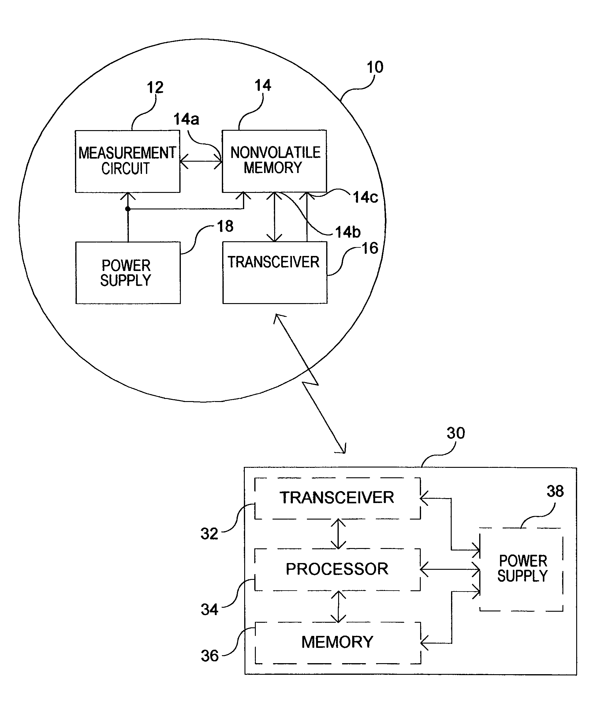
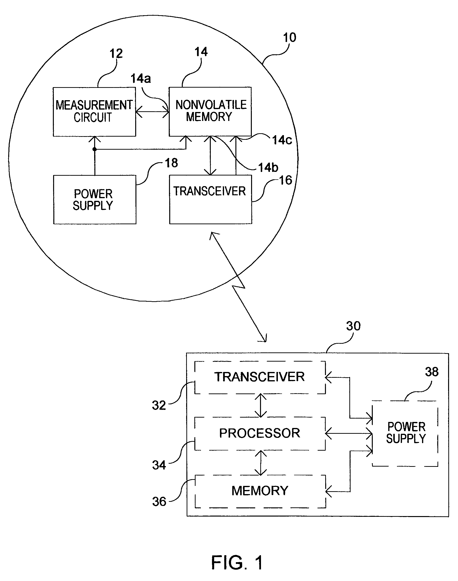
[0021]FIG. 1 shows an exemplary commodity consumption meter 10 according to the present invention and an exemplary external device 30 for use therewith. In general the external device 30 communicates data to and / or from the commodity consumption meter 10. The external device 30 further provides signals to the commodity consumption meter 10 from which elements within the meter 10 derive power for effecting data communication operations.

[0022]To this end, the commodity consumption meter 10 includes a measurement circuit 12, a non-volatile memory 14, a power supply 18, and a transceiver 16. It will be appreciated that the commodity consumption meter 10 may optionally include other devices such as other communication circuitry, an electronic or mechanical display, and other peripheral devices commonly available in commodity meters.

[0023]The exemplary external device 30 includes a transceiver 32, a processor 34, a memory 36 and a power supply 38. The external device 30 may comprise a por...


PUM


Abstract

An arrangement for use in a utility meter includes a non-volatile memory and an RF transceiver. The non-volatile memory has a first and a second port, the first port configured to obtain commodity consumption data. The radio frequency (RF) transceiver is configured to receive and RF signal from an external source and obtain energy from the RF signal and provide the energy to a bias voltage input of the non-volatile memory. The RF transceiver is further operable to perform a data transfer operation responsive to the received RF signal, the data transfer operation including a transfer of meter-related data between the non-volatile memory and the RF transceiver using the second port of the non-volatile memory.

Description

[0001]This application claims the benefit of U.S. Provisional Application Ser. No. 60 / 322,024, filed Sep. 14, 2002.FIELD OF THE INVENTION[0002]The present invention relates generally to utility meters, and more particularly, utility meters having automated meter reading capability.BACKGROUND OF THE INVENTION[0003]Utility meters are devices the measure the consumption or flow of a commodity, such as gas, water or electricity. Traditionally, utility meters measured the consumption of a commodity by a facility, for example, a residence, factory, or commercial establishment. Other utility meters may measure the flow of a commodity out of a facility such as a power generation plant or a distribution network.[0004]In general, however, utility meters measure commodity consumption and retain the commodity consumption data for use by the utility service provider. Commodity consumption data may include the quantity electrical energy consumed or the volume of gas or water consumed. The utility...

Claims


Application Information

Patent Timeline
Patent Type & Authority Patents(United States)
IPC IPC(8): G08C19/16G01D4/00G08C19/02H04Q9/04
CPCG01D4/002G08C19/02H04Q9/00H04Q9/04H04W4/008H04Q2209/60Y02B90/248Y02B90/241Y04S20/32Y04S20/52Y02B90/246Y04S20/42H04W4/80Y02B90/20Y04S20/30
Inventor JUNKER, JOHN P.BURNS, GORDON R.
Owner LANDIS GYR LLC
Why Eureka
Try Eureka