Circuit board for ink jet head, ink jet head having the same, method for cleaning the head and ink jet printing apparatus using the head

a technology of ink jet printing and circuit board, which is applied in the direction of printing, inking apparatus, etc., can solve the problems of insufficient removal of kogations, inability to uniformly and reliably remove kogations, and increase the cost of ink or a limited number of dyes that can be used, so as to achieve reliable high-quality printing and reliably stabilize the characteristic of ink ejection

Active Publication Date: 2011-05-31
CANON KK
View PDF19 Cites 14 Cited by
  • Summary
  • Abstract
  • Description
  • Claims
  • Application Information

AI Technical Summary

Benefits of technology

[0015]The present invention has been accomplished with a view to overcoming the problems described above and it is an object of this invention to make it possible to perform a reliable high-quality printing by removing kogations deposited on the heat application portion uniformly and reliably to stabilize an ink ejection characteristic.
[0016]Another object of this invention is to make it possible to perform the cleaning during a session of printing operation without requiring a special and cumbersome cleaning procedure done by a cleaning company or by a user.
[0028]In the first through fourth aspect, the upper protective layer is formed of a material containing a metal that is dissolved by an electrochemical reaction and which does not form such an oxide film on heating as will hinder the dissolution. With this arrangement, a reliable electrochemical reaction can be produced to dissolve the surface layer of the upper protective layer, allowing for a uniform, reliable removal of kogation on the heat application portion. This in turn stabilizes an ejection characteristic of the ink jet head, assuring a reliable, high-quality image printing.
[0030]In the fifth through eighth aspect, as in the first through fourth aspect, the kogation on the upper protective layer can be removed by dissolving the surface layer of the upper protective layer by the electrochemical reaction. Further, when a voltage is applied between the upper protective layer and the electrode, the electrode polarity of the upper protective layer can be reversed. Thus, if an ink component adheres to the upper protective layer during the process of the electrochemical reaction, it can be dispersed in the ink. Therefore, the electrochemical reaction can be produced in a more appropriate way, assuring a more reliable removal of kogations. It is therefore possible to stabilize the ejection characteristic of the ink jet head, enhance reliability and form a high-quality printed image.
[0031]In the ninth aspect, as in the first through fourth aspect, the kogation on the upper protective layer can be removed by dissolving the surface layer of the upper protective layer by the electrochemical reaction. Further, since the voltage application to the upper protective layer to cause the electrochemical reaction is performed in connection with the ink discharging recovery operation, bubbles formed on the upper protective layer can be discharged along with the ink. This in turn enables the electrochemical reaction to be conducted more appropriately, removing kogation more reliably.

Problems solved by technology

This, however, gives rise to other problems, such as an increased cost of ink or a limited number of kinds of dyes that can be used.
However, an examination of the technique described in Japanese Patent Application Laid-open No. 9-29985 (1997) by the inventors of this invention have found a problem that the deposited kogations sometimes fail to be removed sufficiently.
That is, since the electrochemical reaction is hindered over the surface of the heat application portion where kogations are deposited, the kogations cannot be removed uniformly and reliably.
There is, however, a problem that the cleaning cannot be done at least during the printing operation performed by the user.

Method used


Image

  • Circuit board for ink jet head, ink jet head having the same, method for cleaning the head and ink jet printing apparatus using the head
  • Circuit board for ink jet head, ink jet head having the same, method for cleaning the head and ink jet printing apparatus using the head
  • Circuit board for ink jet head, ink jet head having the same, method for cleaning the head and ink jet printing apparatus using the head

Examples


first embodiment

2. First Embodiment

[0071]2.1 Construction of Ink Jet Head

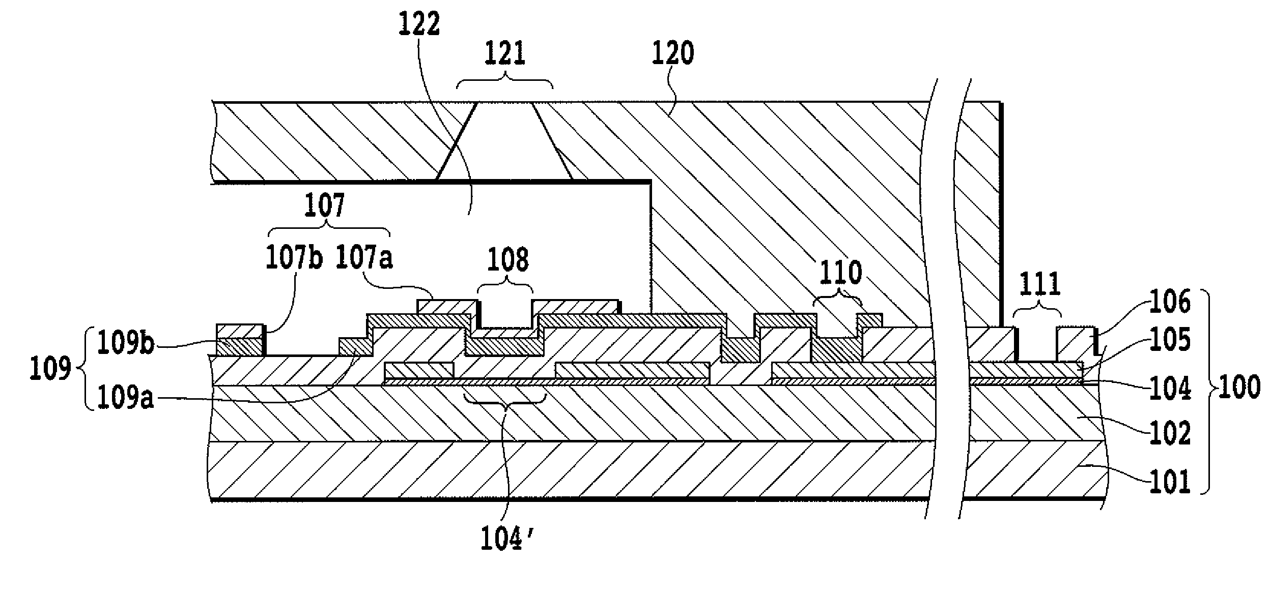
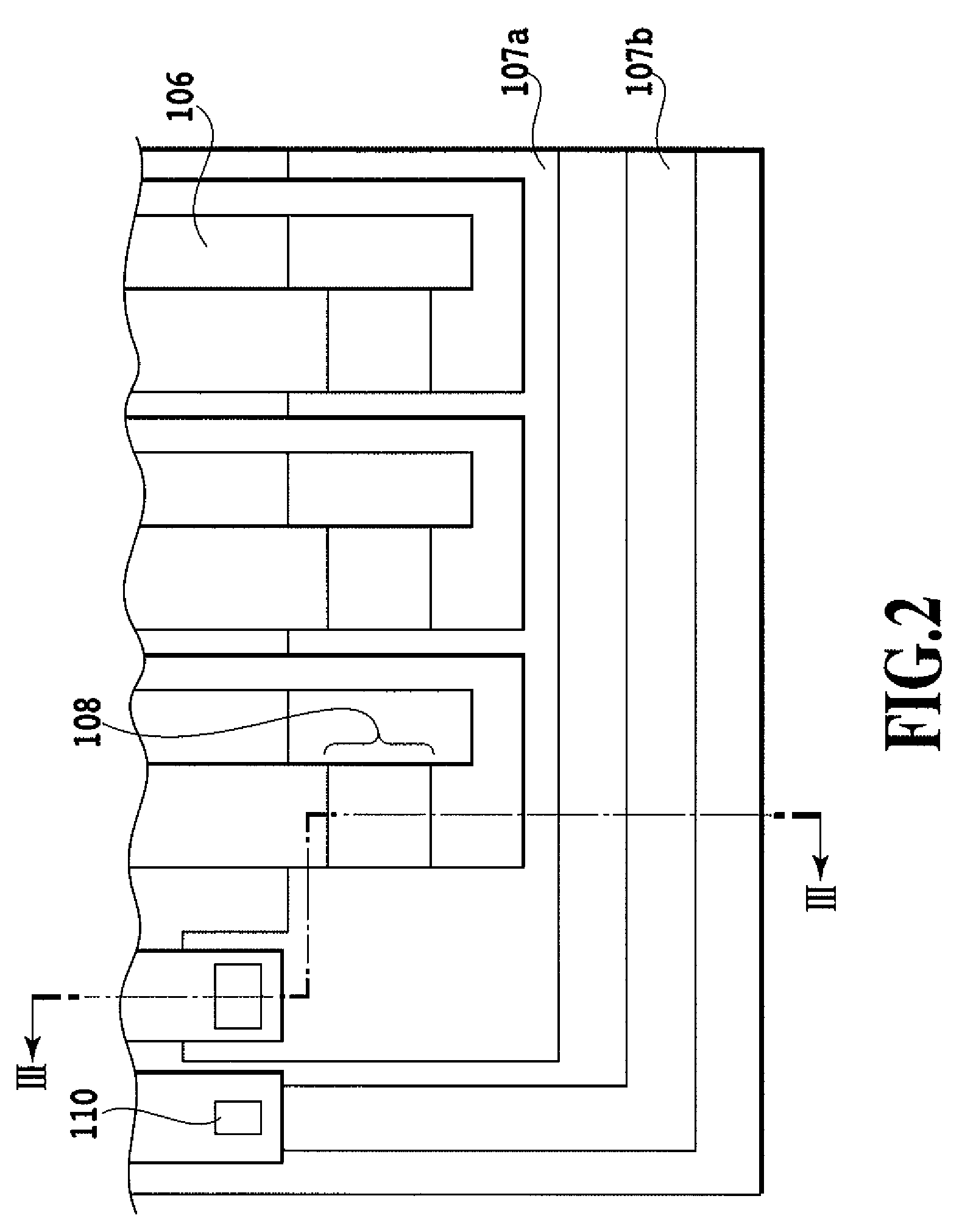
[0072]FIG. 2 is a schematic plan view showing a heat application portion of the ink jet head circuit board (hereinafter simply referred to also as the circuit board) according to the first embodiment of this invention. FIG. 3 is a schematic cross-sectional view of the circuit board vertically cut along the line III-III of FIG. 2.

[0073]In FIG. 2 and FIG. 3, denoted 101 is a silicon substrate. Denoted 102 is a heat accumulating layer formed of a thermally oxidized film, SiO film or SiN film, 104 is a heating resistor layer, and 105 is an electrode wiring layer for wires formed of such metal materials as Al, Al—Si and Al—Cu. A heating portion 104′ as the electrothermal transducer is formed by removing a part of the electrode wiring layer 105 to form a gap and then exposing the heating resistor layer in that part. The electrode wiring layer 105 is connected to a drive element circuit or external power supply terminal (not shown) t...

example 1

[0105]Using a plurality of ink jet heads manufactured according to the process described above, kogation removing experiments were conducted. The experiments involve energizing the heating portion under a specified condition to deposit kogations on the heat application portion 108 and then applying a voltage to the upper protective layer 107 to remove the kogations. The ink used was BCI-6E M (Canon make).

[0106]First, a drive pulse with a magnitude of 20 V and a width of 1.5 μs was applied to the heating portion 5.0×10⁶ times at a frequency of 5 kHz.

[0107]FIG. 12A schematically shows a state immediately after the application of the voltage. An impure substance K called a kogation was deposited nearly uniformly over the heat application portion 108, as shown in FIG. 12A. It was confirmed that performing a printing operation using the ink jet head in this state resulted in a poor print quality because of the deposited kogation K.

[0108]Next, a DC voltage of 10 V was applied to the exter...

example 2

[0112]Next, in the same process as the example 1 except that the upper protective layer 107 was formed of Ru, a plurality of ink jet heads of example 2 were manufactured and subjected to the same kogation removing experiment as described above. The kogation removing experiment was conducted by energizing the ink jet head under the same condition as described above, observing the kogation deposit state and the print quality before and after the kogation removing operation, and measuring the height difference between the pattern ends of the upper protective layer area 107a and the adhesive layer 109.

[0113]It was verified that the kogation on the heat application portion could be removed and the print quality recovered also when Ru was used for the upper protective layer 107 as in the case of Ir.

[0114]It is known that the dry etching is easily performed with Ru compared with Ir. So, Ru allows for an easy manufacture of the ink jet head circuit board.

[0115](Example for Comparison)

[0116]...


PUM


Abstract

In an ink jet head using a thermal energy for ejecting ink, this invention aims to reliably and uniformly remove kogations deposited on a heat application portion in contact with the ink. To realize this objective, the upper protective layer is arranged in an area including the heat application portion so that it can be electrically connected to serve as an electrode which causes an electrochemical reaction with the ink. The upper protective layer is formed of a material containing a metal which is dissolved by the electrochemical reaction and which does not form, on heating, an oxide film which hinders the dissolution. With this arrangement, a reliable electrochemical reaction can be produced to dissolve a surface layer of the upper protective layer, thereby removing kogations on the heat application portion reliably and uniformly.

Description

BACKGROUND OF THE INVENTION[0001]1. Field of the Invention[0002]The present invention relates to an ink jet head to eject ink onto a print medium for printing according to an ink jet method and also relates to a circuit board for the head, a method and a device for cleaning the head and an ink jet printing apparatus using the head.[0003]2. Description of the Related Art[0004]An ink jet printing method disclosed in U.S. Pat. No. 4,723,129 or 4,740,796 can perform a high-speed, high-quality printing by generating a bubble in ink using a thermal energy and can easily be upgraded to have a color printing capability and reduced in size. Because of these advantages, this method has become a mainstream of the ink jet printing method in recent years.[0005]A general construction of the head (ink jet head) used for the ink jet printing comprises a plurality of ink ejection orifices, a plurality of liquid paths communicating to the ink ejection orifices, and a plurality of electrothermal trans...

Claims


Application Information

Patent Timeline
Patent Type & Authority Patents(United States)
IPC IPC(8): B41J2/165
CPCB41J2/14072B41J2/16517B41J2/14129B41J2202/03B41J2002/16561
Inventor SAKAI, TOSHIYASUSAITO, ICHIROOZAKI, TERUOYOKOYAMA, SAKAIMATSUI, TAKAHIROHATSUI, TAKUYASHIBATA, KAZUAKI
Owner CANON KK
Why Eureka
Try Eureka