

Moisture-detecting shaft for use with an electro-mechanical surgical device
- Summary
- Abstract
- Description
- Claims
- Application Information
AI Technical Summary
Problems solved by technology
Method used
Image

Examples
Embodiment Construction
[0058]Those skilled in the art will gain an appreciation of the present invention from a reading of the following description when viewed in conjunction with the accompanying drawings of FIGS. 1 to 32, inclusive. The individual reference characters designate the same or similar elements throughout the several views.
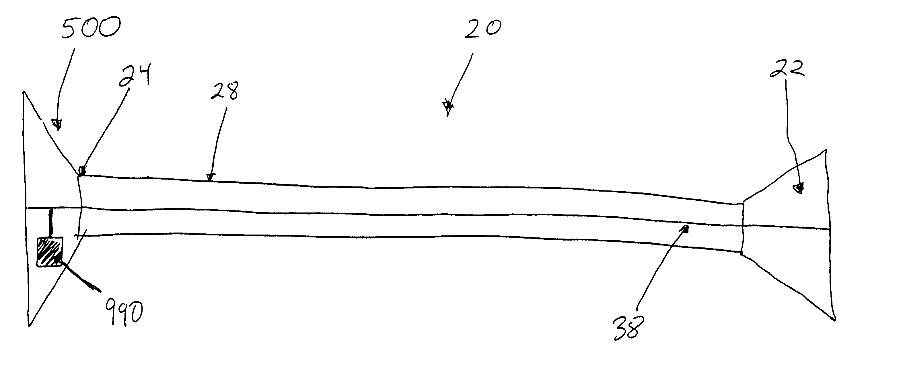
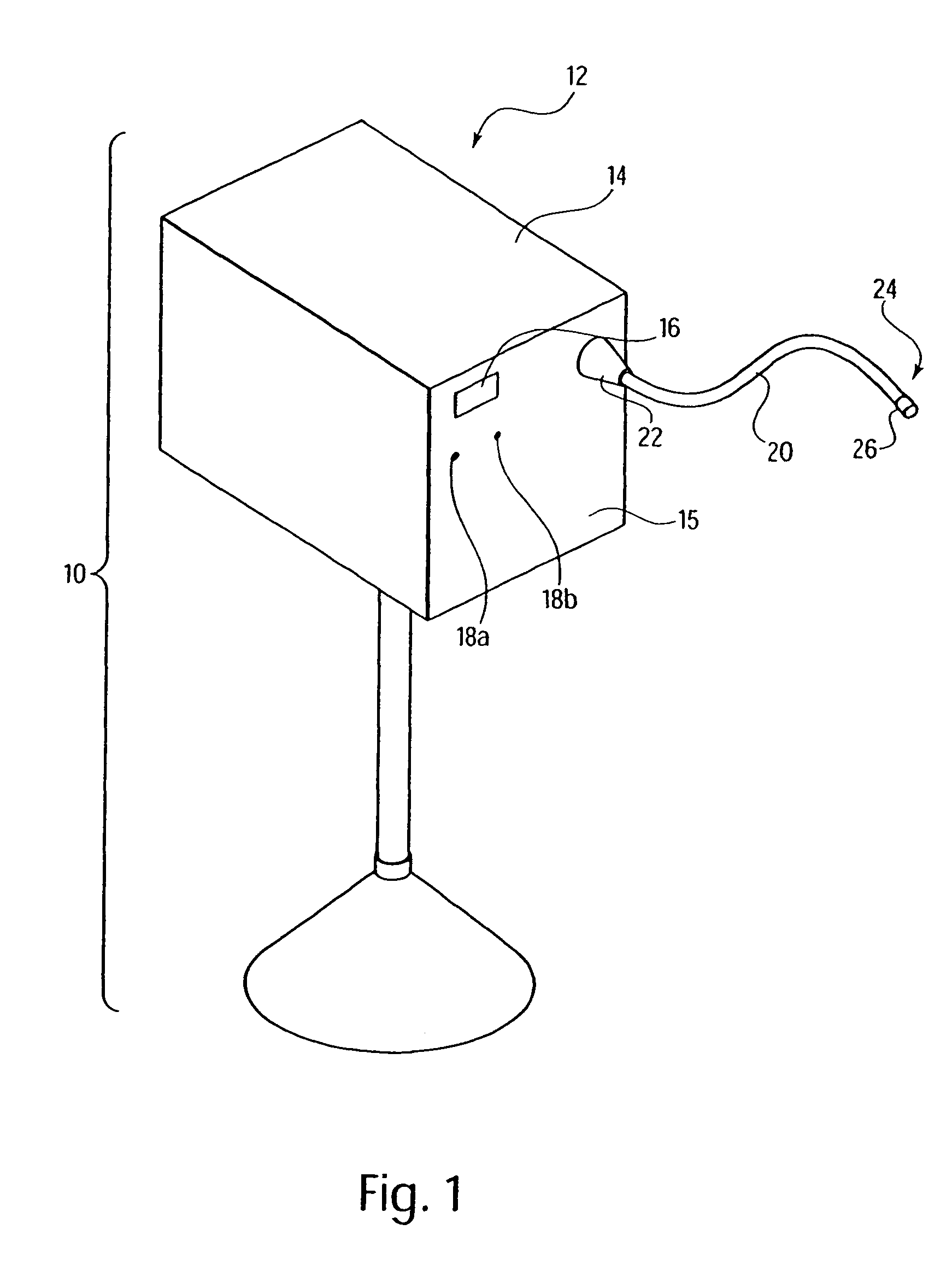
[0059]Referring to FIG. 1, there is seen a perspective view of an electro-mechanical surgical device 10 according to an example embodiment of the present invention. Electro-mechanical surgical device 10 may include, for example, a remote power console 12, which includes a housing 14 having a front panel 15. Mounted on front panel 15 are a display device 16 and indicators 18a, 18b, which are more fully described hereinbelow. A shaft 20 may extend from housing 14 and may be detachably secured thereto via a first coupling 22. The shaft 20 may be flexible, rigid, articulable, articulatable, etc. Although shaft 20 is referred to below as a flexible shaft 20, it should be under...
PUM
 Abstract
Description
Claims
Application Information