Modular LED unit incorporating interconnected heat sinks configured to mount and hold adjacent LED modules

a module led module and heat sink technology, applied in the field of led arrays, can solve the problems of reducing the development effort of led modules for common lighting applications, affecting the production and assembly of lighting fixtures, and requiring a lot of lighting development effort, so as to facilitate the manufacture and assembly of lighting fixtures, and reduce product development costs

Active Publication Date: 2011-05-31
IDEAL IND LIGHTING LLC
View PDF151 Cites 46 Cited by
  • Summary
  • Abstract
  • Description
  • Claims
  • Application Information

AI Technical Summary

Benefits of technology

[0009]Another object of the invention is to provide an improved modular LED unit that is readily adaptable for a wide variety of common lighting uses, including many that have predominantly been served in the past by HID lamps or other common light sources.
[0010]Another object of the invention is to provide an improved modular LED unit that significantly reduces product development costs for widely varying lighting fixtures that utilize LED0-array technology.
[0011]Another object of the invention is to provide an improved modular LED unit that facilitates manufacture and assembly of lighting fixtures using LED modules as light source.
[0017]In preferred embodiments, the flange hook of the first side-fin is preferably at the distal fin-edge of the first side-fin, where it is engaged by the distal fin-edge of the second side-fin of an adjacent heat sink. This provides particularly stable engagement of two adjacent heat sinks.
[0023]Such spacer members and selected spacer member placement provide a great deal of flexibility in lighting-fixture configuration, allowing use of LED modules of a previously-chosen “standard” size for fixtures of widely varying dimensions and light-output requirements. For example, a fixture of a particular desired dimension and light requirement can use a certain number of LED modules, with one or more spacer members accommodating unused space an / or spreading the LED modules to temper the intensity of light output. Spacer members may themselves have “standard” sizes and shapes to accommodate a wide variety of LED lighting-fixture configurations and sizes.

Problems solved by technology

Nearly everything about the technology is different and significant problems are encountered in the development of lighting fixture and systems utilizing LED modules.
Furthermore, use of LED modules for common lighting applications requires much more than the typical lighting development efforts required in the past with HID or other more common light sources.
In particular, creating LED-module-base lighting fixtures for widely varying common lighting applications—such as applications involving different light-intensity requirements, size requirements and placement requirements—is a difficult matter.
In general, harnessing LED module technology for varying common lighting purposes is costly because of difficulty in adapting to specific requirements.
There are significant barriers and problems in product development.

Method used


Image

  • Modular LED unit incorporating interconnected heat sinks configured to mount and hold adjacent LED modules
  • Modular LED unit incorporating interconnected heat sinks configured to mount and hold adjacent LED modules
  • Modular LED unit incorporating interconnected heat sinks configured to mount and hold adjacent LED modules

Examples


Embodiment Construction

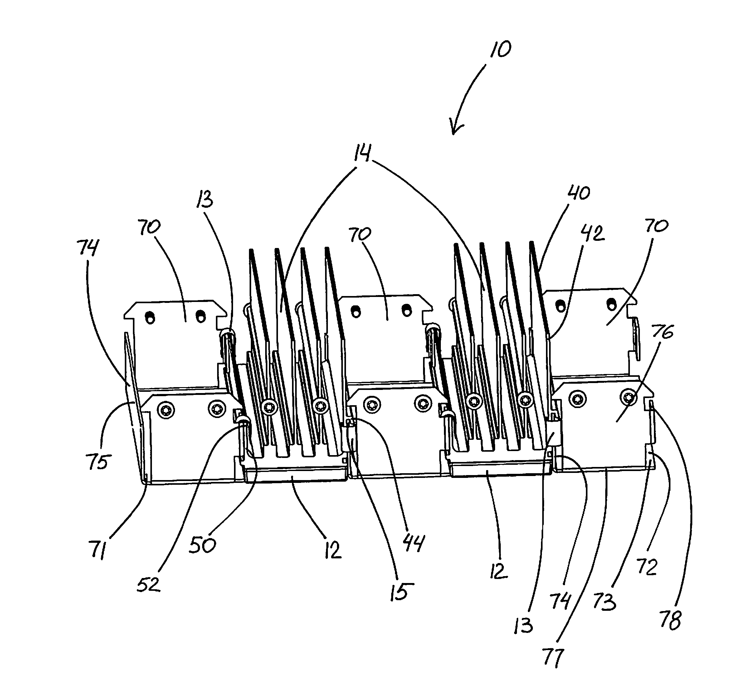
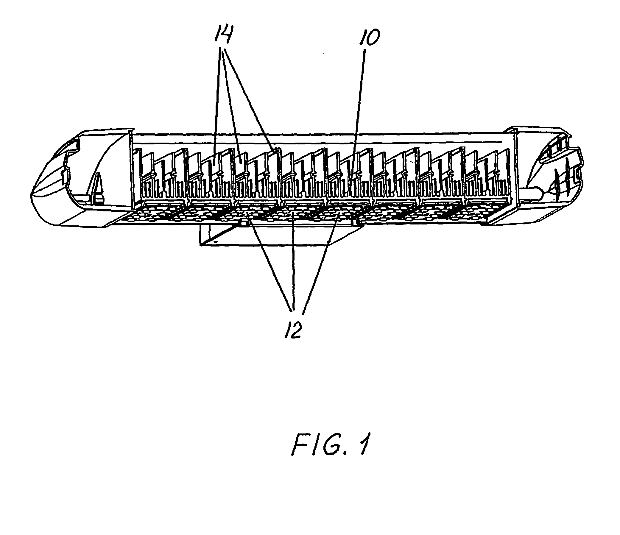
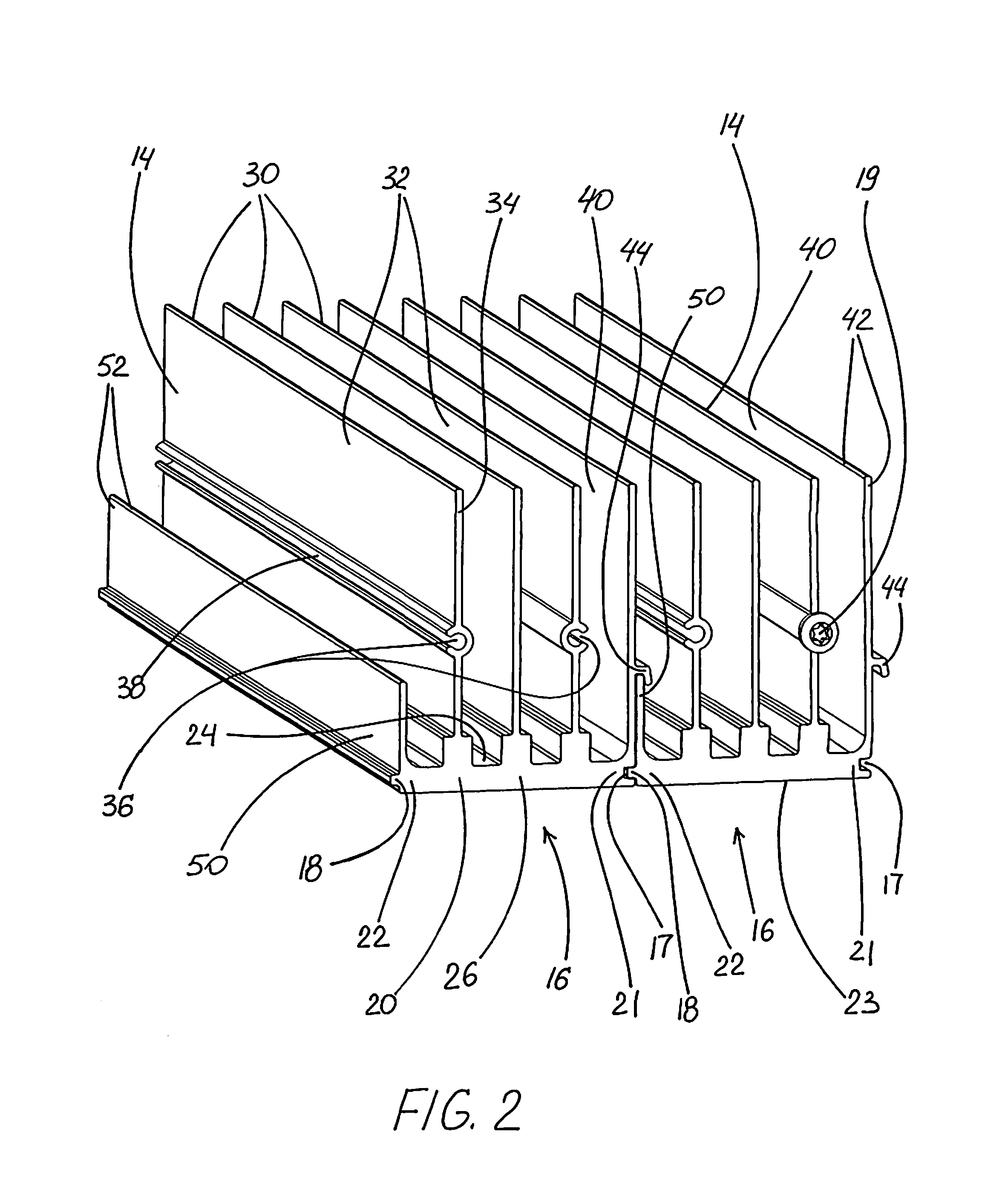
[0031]FIGS. 1-3 illustrate a preferred modular LED unit 10 in accordance with this invention. Modular LED unit 10 has a number of LED modules 12 separately mounted on individual interconnected heat sinks 14. Each heat sink 14 separately supports one LED module 12.

[0032]Each heat sink 14 has a base 20 with a flat back surface 23, an opposite surface 24, two base-ends 26, a first side 21 and a second side 22. Heat sink 14 also includes a plurality of inner-fins 30 projecting from opposite surface 24 of base 20, a first side-fin 40 and a second side-fin 50, each of the side-fins also projecting from opposite surface 24. First and second side-fins terminate at distal fin-edges 42 and 52, respectively. First side-fin 40 includes a flange hook 44 at distal fin-edge 42. Flange hook 44 is positioned to engage distal fin-edge 52 of second side-fin 50 of an adjacent heat sink 14.

[0033]Each heat sink 14 also includes a first lateral support 60A and a second lateral support 60B projecting from ...


PUM


Abstract

A modular LED unit having a number of LED modules separately mounted on individual interconnected preferably-extruded heat sinks, each heat sink having: a base configured to engage and hold an LED module in place and, in preferred forms, to facilitate the ganging of heat-sink / LED modules; and a plurality of fins, including inner-fins and side-fins, projecting from the opposite surface of the base and extending therealong, the side-fins having interlocking features to facilitate the ganging of heat-sink / module units together and, in preferred forms, to facilitate interconnection of the modular LED unit to other portions of a lighting fixture.

Description

RELATED APPLICATION[0001]This application is a continuation-in-part of patent application Ser. No. 11 / 541,905, filed Sep. 30, 2006, currently pending. The contents of the parent application are incorporated herein by reference.FIELD OF THE INVENTION[0002]This invention relates to lighting fixtures and, more particularly, to the use of LED arrays (modules) for various lighting fixtures and applications, particularly lighting application for which HID lamps or other common light sources have most typically been used.BACKGROUND OF THE INVENTION[0003]In recent years, the use of light-emitting diodes (LEDs) for various common lighting purposes has increased, and this trend has accelerated as advances have been made in LEDs and in LED arrays, often referred to as “LED modules.” Indeed, lighting applications which previously had been served by fixtures using what are known as high-intensity discharge (HID) lamps are now beginning to be served by fixtures using LED-array-bearing modules. Su...

Claims


Application Information

Patent Timeline
Patent Type & Authority Patents(United States)
IPC IPC(8): F21V29/00F21V21/00H01L33/64
CPCF21S2/005F21V29/004F21V29/763F21V29/75F21K9/00F21Y2101/02Y10S362/80F21W2131/103F21Y2115/10
Inventor WILCOX, KURTWALCZAK, STEVEN R.PATKUS, STEVEN J.RUUD, ALAN J.
Owner IDEAL IND LIGHTING LLC
Why Eureka
Try Eureka