Board-to-board connector system

a technology of connectors and boards, applied in the direction of semiconductor devices for light sources, coupling device connections, lighting and heating apparatus, etc., can solve the problems of difficult and impractical removal of interior circuit boards

Active Publication Date: 2011-06-14
TYCO ELECTRONICS LOGISTICS AG (CH)
View PDF14 Cites 39 Cited by
  • Summary
  • Abstract
  • Description
  • Claims
  • Application Information

AI Technical Summary

Problems solved by technology

When many boards are used and arranged in an-end-to-end stacked configuration, it is difficult and impractical to remove an interior circuit board without also removing every othe...

Method used


Image

  • Board-to-board connector system
  • Board-to-board connector system
  • Board-to-board connector system

Examples


Embodiment Construction

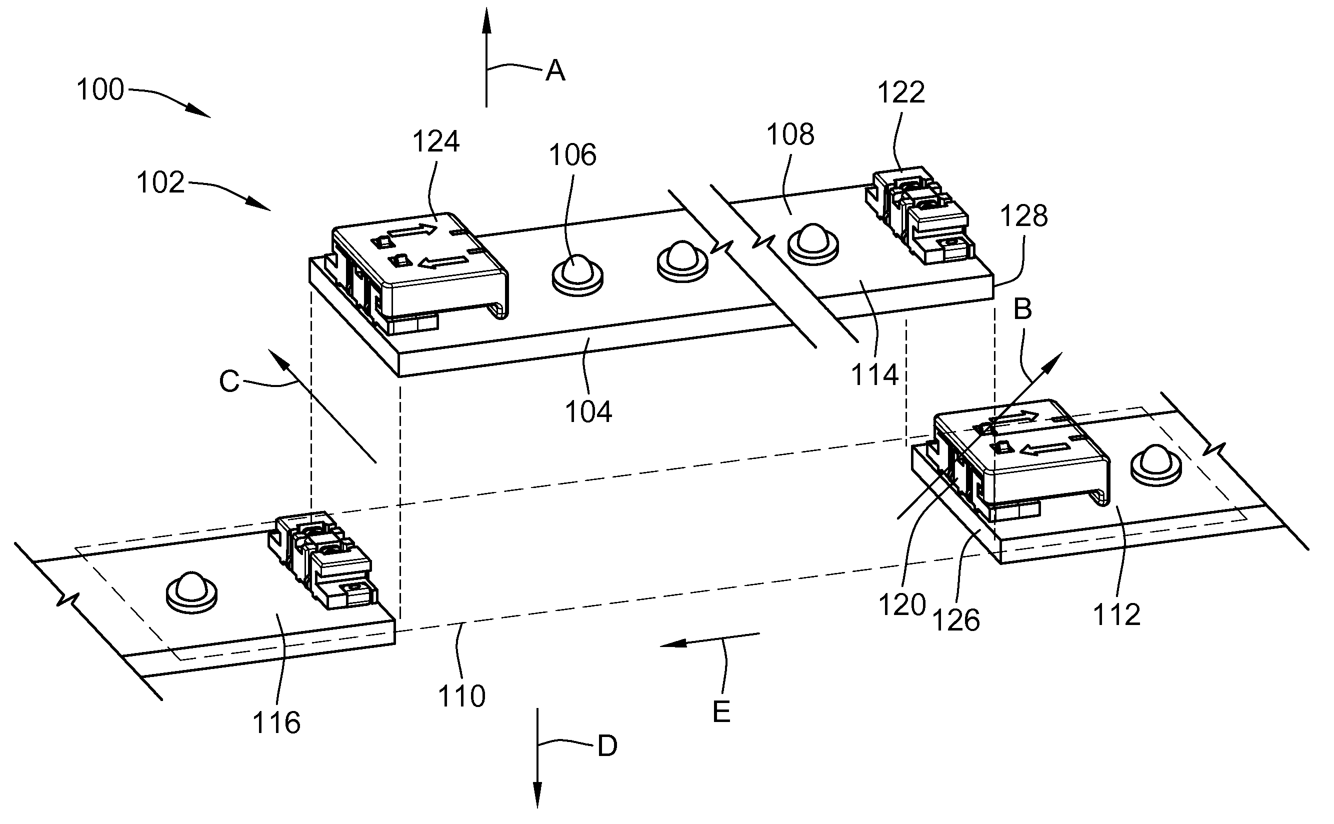
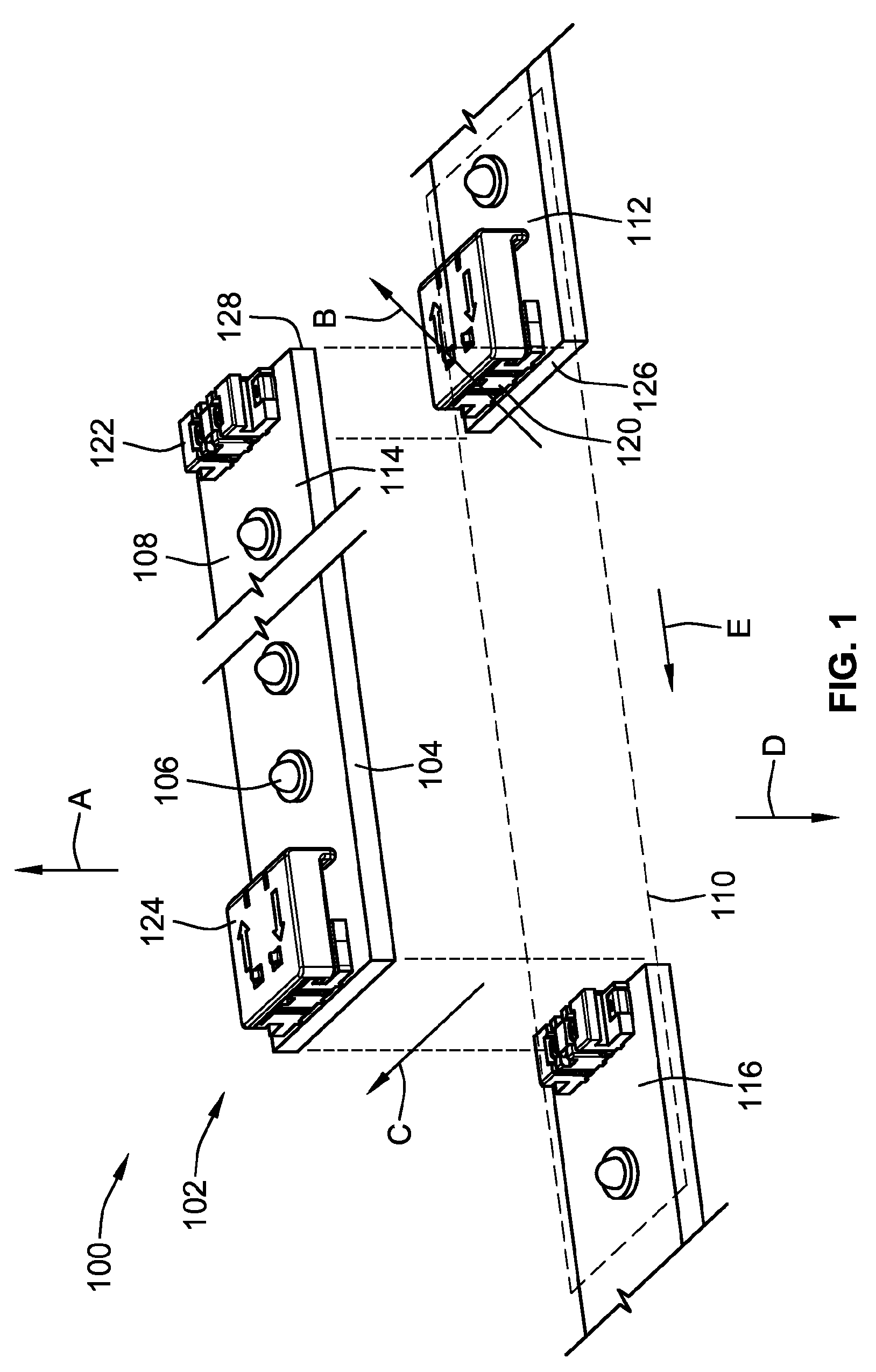
[0026]FIG. 1 illustrates a connector system 100 formed in accordance with an exemplary embodiment. The connector system 100 utilizes connector assemblies 102 to interconnect electrical components 104 to one another. In the illustrated embodiment, electrical components 104 constitute circuit boards 104 arranged end-to-end in a stacked configuration. Any number of circuit boards 104 may be connected together. In an exemplary embodiment, the connector system 100 is an electrical system that distributes electrical power from one electrical component 104 to the next electrical component 104. Alternatively, the connector system 100 may additionally or alternatively transmit electrical control signals (e.g. data).

[0027]The circuit boards 104 each may be light boards that include a plurality of light emitting diodes (LEDs) 106 mounted to a top surface 108 of the circuit boards 104. The LEDs 106 may be arranged in any pattern to provide a desired illumination effect. The circuit boards 104 g...


PUM


Abstract

A connector system includes a first contact module terminated to a first circuit board proximate to an edge of the first circuit board. The first contact module has a first housing holding first contacts that are electrically connected to the first circuit board. The connector system also includes a second contact module terminated to a second circuit board proximate to an edge of the second circuit board. The second contact module having a second housing holding second contacts that are electrically connected to the second circuit board. A jumper module electrically connects the first contacts and the second contacts, where the jumper module is movable independently of the first and second housings between a mated state and an unmated state. The first and second contacts are electrically connected in the mated state. When the jumper module is in the unmated state, the first circuit board and the second circuit board can be brought together from a plurality of different directions. The jumper module is moved to the mated state after the first and second circuit boards are brought together.

Description

BACKGROUND OF THE INVENTION[0001]The subject matter herein relates generally to electrical connector systems, and more particularly, to connector systems for electrically connecting adjacent circuit boards together.[0002]Connector assemblies are required to provide electrical power or electrical or electronic control signals between components, such as power sources, computers, auxiliary hardware, or other electrical components within an electrical or electronic system. Often, these components contain panel members, such as circuit boards, which are populated with miniaturized components to provide the desired electrical control. One example of an electrical system that utilizes such circuit boards and connector assemblies is a lighting system that utilizes multiple light boards having light emitting diodes (LEDs) connected to the circuit boards. The light boards are arranged end-to-end and power is transferred from one light board to the next by connector assemblies at the ends of ...

Claims


Application Information

Patent Timeline
IPC IPC(8): H01R12/00
CPCH01R12/716H01R31/085Y10S439/928F21V23/06F21Y2103/10F21Y2115/10H05K1/14H01R12/55
Inventor DAILY, CHRISTOPHER GEORGENARANG, ROHANMOSTOLLER, MATTHEW EDWARD
Owner TYCO ELECTRONICS LOGISTICS AG (CH)
Why Eureka
Try Eureka