
Universal joint having slip bush

a universal joint and slip bush technology, applied in the field of universal joints, can solve the problems of reducing the safety factor in relation to the strength of torsional fracture, unable to secure the safety of drivers, and unable to perform steering, so as to reduce the sliding frictional force

Active Publication Date: 2011-07-05
HL MANDO CORP
View PDF4 Cites 0 Cited by
  • Summary
  • Abstract
  • Description
  • Claims
  • Application Information

AI Technical Summary

Benefits of technology

"The present invention provides a universal joint that can smoothly collapse when axial pressure is applied while rotational torque is applied, and also improves torsional fracture strength. The universal joint includes a tube, a slip bush, and a shaft, with one or more rows of guide holes and guide balls fitted in the guide holes. The guide balls reduce sliding frictional force while producing rolling frictional force, and also serve as supports when torsional fracture torque is applied to the slip bush, improving safety factor."

Problems solved by technology

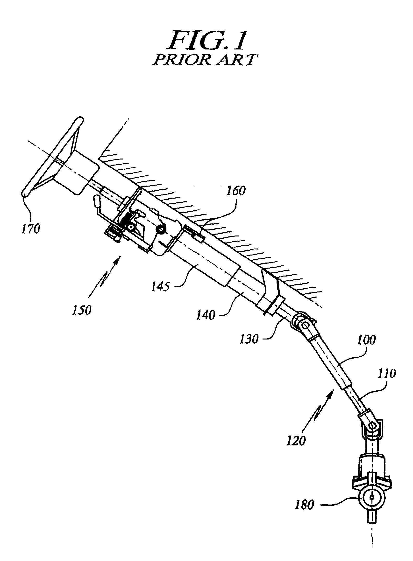
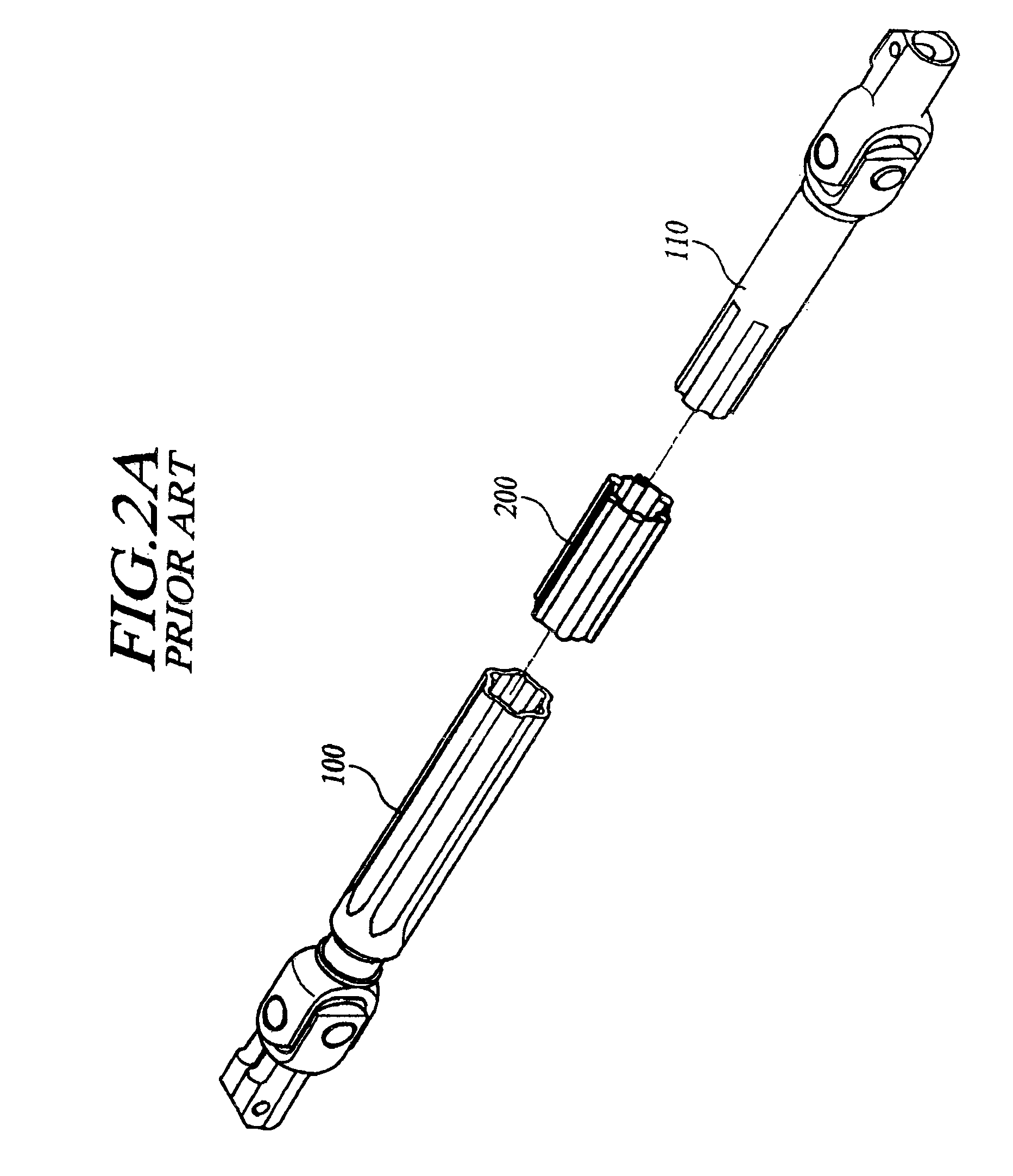
As a result, there is a problem in that the sliding frictional force between the slip bush 200 and tube 100 increases and a safety factor in relation to the torsional fracture strength decreases.
However, when the above-mentioned conventional slip bush 200 is employed, there is a problem in that when an impact with torsion is applied to the universal joint, it is impossible to secure driver's safety because the universal joint does not properly collapse due to large frictional force between the solid parts 220 of the slip bush 200 and the inner circumferential surface of the tube 100.
If so, due to the property of the material of the slip bush which is equal to that of the solid parts, the solid parts may be fractured when strong rotational force is applied within a short period of time, and when such a phenomenon occurs, it is impossible to perform steering, thereby causing a serious problem in safety.
This problem is caused when the above-mentioned safety factor in relation to the torsional fracture strength decreases.

Method used


Image

  • Universal joint having slip bush
  • Universal joint having slip bush
  • Universal joint having slip bush

Examples


Embodiment Construction

[0029]Hereinafter, a preferred embodiment of the present invention will be described with reference to the accompanying drawings. In the following description and drawings, the same reference numerals are used to designate the same or similar components, and so repetition of the description on the same or similar components will be omitted.

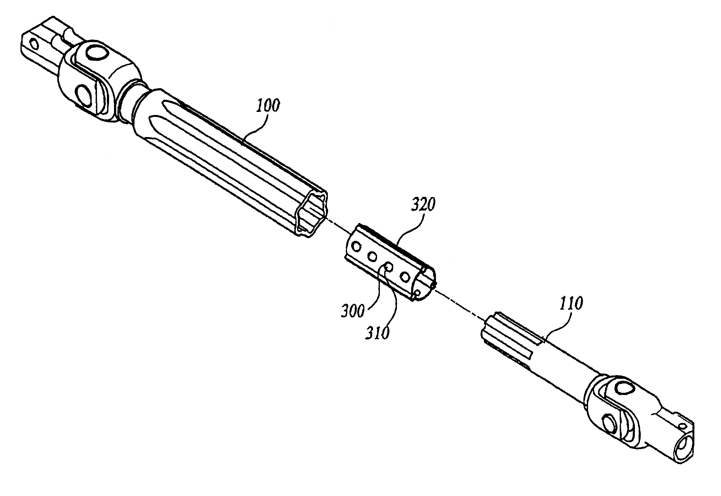
[0030]FIG. 3A is an exploded perspective view of a universal joint according to an embodiment of the present invention. As shown in FIG. 3A, the universal joint includes a slip bush 320 according to the present invention, wherein one or more rows of guide holes 300 formed by perforating the circumferential wall of the slip bush 320 are arranged in the longitudinal direction of the slip bush 320; one or more guide balls 310 are fitted in the guide holes 300, respectively; and one or more C-type parts 210 are longitudinally formed on the circumferential wall of the slip bush 320.

[0031]A shaft 110 of the universal joint 120 connected to a steering sh...


PUM


Abstract

Universal joint having slip bush including a tube, a slip bush inserted into the tube, and a shaft inserted into and slidably engaged with the tube via the slip bush. The universal joint further includes: one or more rows of guide holes formed by perforating a circumferential wall of the slip bush, the rows being arranged in the longitudinal direction of the slip bush; one or more guide balls fitted in the guide holes, respectively; and one or more C-type parts longitudinally formed on the circumferential wall of the slip bush. When axial pressure is applied to the universal joint in a state in which rotational torque is applied to the universal joint, the guide balls fitted in the guide holes come into contact with the inner circumferential surface of the tube, thereby reducing sliding frictional force while producing rolling frictional force so that the universal joint can be smoothly collapsed. In addition, the guide balls serve as supports when torsional fracture torque is applied to the slip bush, thereby improving the torsional fracture strength, which in turn improves a safety factor.

Description

CROSS-REFERENCE TO RELATED APPLICATION[0001]This non-provisional application claims priority under 35 U.S.C §119(a) on Patent Application No. 10-2007-0036030 filed in Korea on Apr. 12, 2007, the entire contents of which are hereby incorporated by reference.BACKGROUND OF THE INVENTION[0002]1. Field of the Invention[0003]The present invention relates to a universal joint. More particularly, the present invention relates to a universal joint constructed in such a manner that when axial pressure is applied to the universal joint in a state in which rotational torque is applied to the universal joint, one or more guide balls fitted in one or more rows of guide holes formed through a circumferential wall of a slip bush come into contact with the inner circumferential surface of the tube, whereby the guide balls reduce sliding frictional force while producing rolling frictional force so that the universal joint can be smoothly collapsed, and that when torsional fracture torque is applied t...

Claims


Application Information

Patent Timeline
Patent Type & Authority Patents(United States)
IPC IPC(8): F16C3/03
CPCF16D3/065B62D1/20F16C3/035F16C2326/24B62D1/16B62D1/19
Inventor JUNG, YOUNG-SOCK
Owner HL MANDO CORP
Learn More