System and method for distributed IP telephony tracking

Active Publication Date: 2011-07-05
CISCO TECH INC
View PDF11 Cites 18 Cited by
  • Summary
  • Abstract
  • Description
  • Claims
  • Application Information

AI Technical Summary

Benefits of technology

[0004]In accordance with the present invention, the disadvantages and problems associated with telephony filtering have been substantially

Problems solved by technology

There are, however, a number of drawbacks to embedding the information in existing protocols.
Embedding the info

Method used


Image

  • System and method for distributed IP telephony tracking
  • System and method for distributed IP telephony tracking
  • System and method for distributed IP telephony tracking

Examples


Embodiment Construction

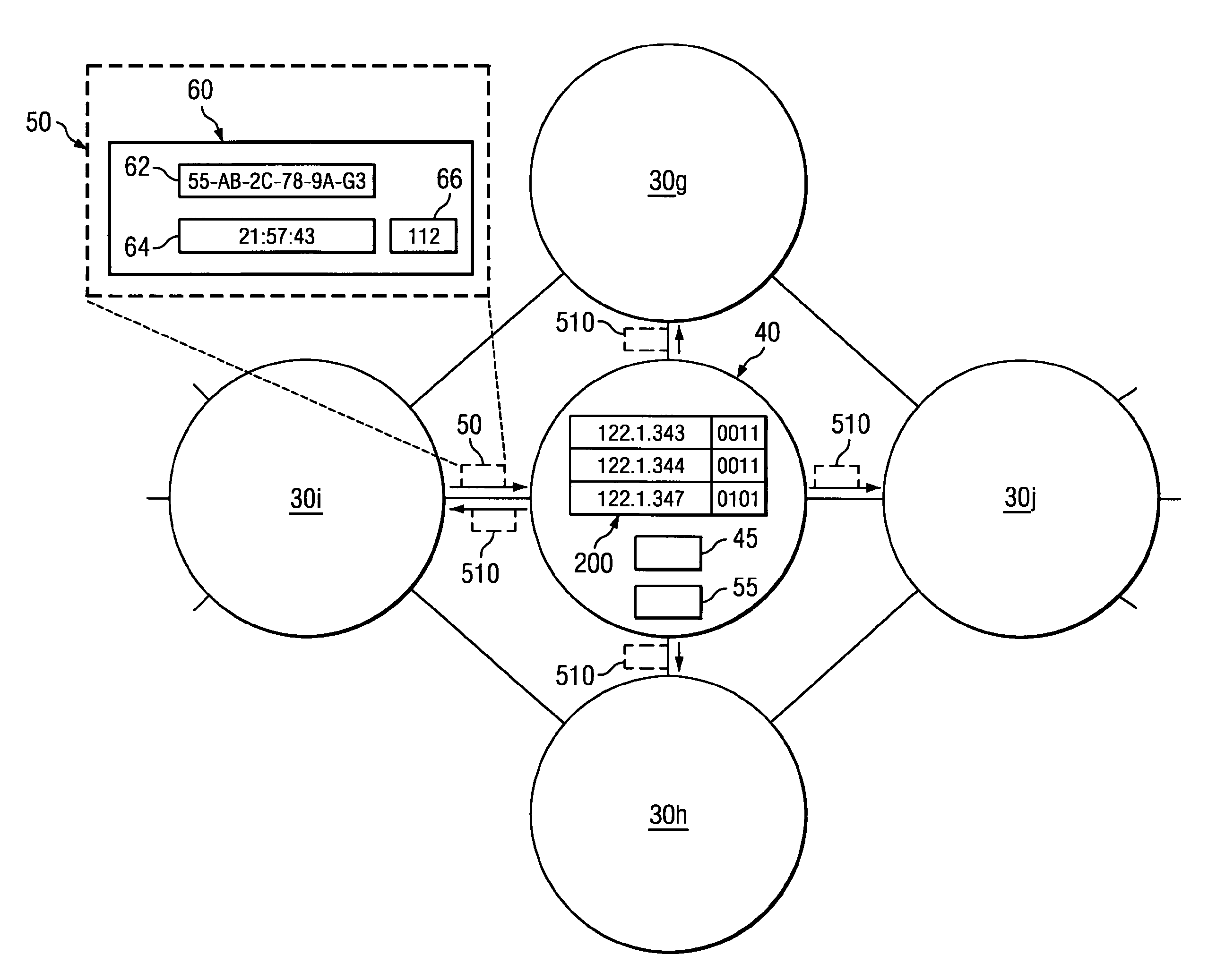
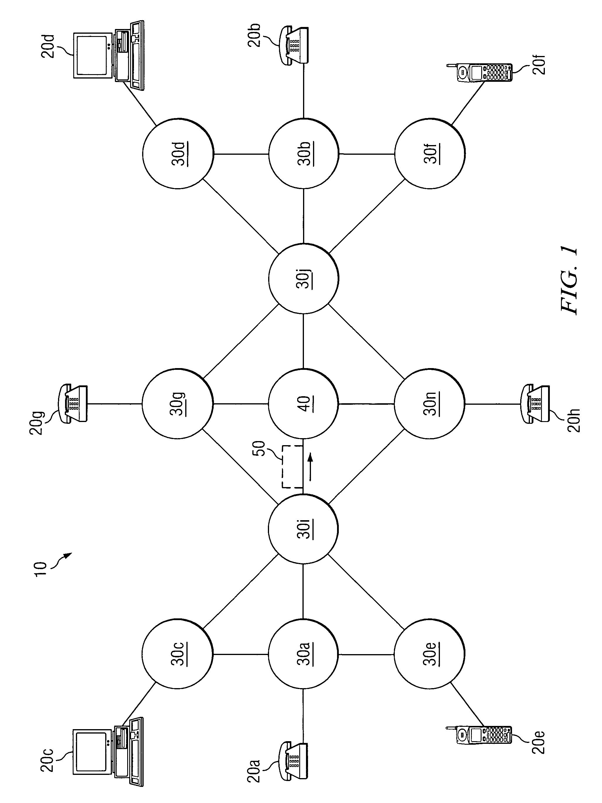
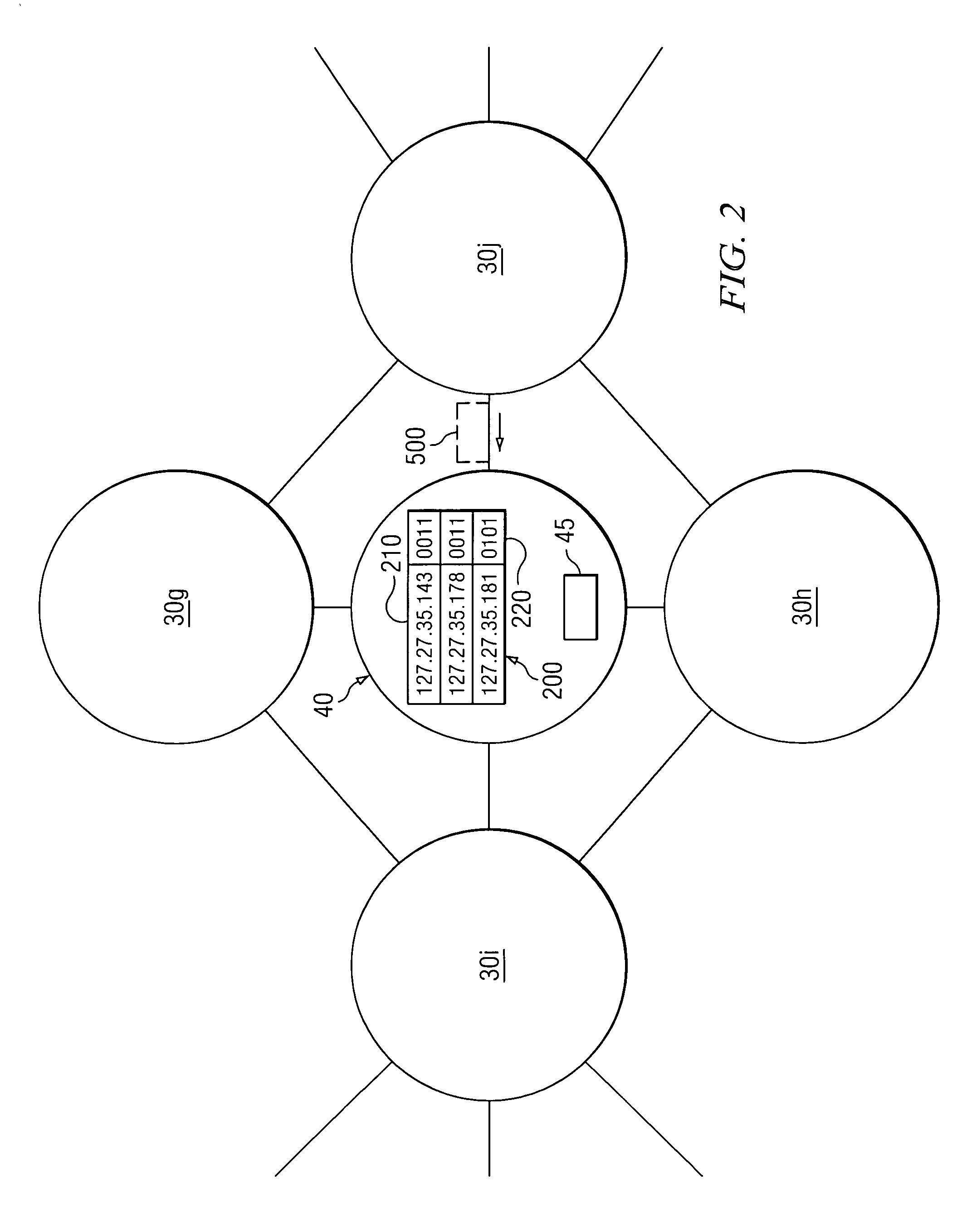
[0021]FIG. 1 illustrates a communication system 10, according to a particular embodiment. Communication system 10 includes endpoints 20, nodes 30, and filter nodes 40. Nodes 30 and filter node 40 support communication between endpoints 20 by transmitting a call along a path between endpoints 20. Additionally, filter node 40 determines a filter status of a call received on communication network 30 and, after establishing capabilities of nodes 30, communicates the filter status to one or more nodes 30 based on the capabilities of nodes 30. Nodes 30 may then initiate filter actions with respect to the call, based on the filter status. Furthermore, the filter status may be propagated along the path, both upwardly and downwardly, providing end-to-end tracking and filtering services.

[0022]By distributing filter functionality and tracking a call as the call progresses through communication system 10, communication system 10 is able to provide differentiated service, better network manageme...


PUM


Abstract

A method of filtering telecommunication service includes receiving a call that includes a call identifier. The method also includes determining a filter status of the call and transmitting a notification message to a remote node. The notification message identifies the call identifier and the filter status of the call.

Description

TECHNICAL FIELD OF THE INVENTION[0001]This invention relates in general to telecommunications, and more particularly to a system and method for distributed telephony tracking and / or filtering.BACKGROUND OF THE INVENTION[0002]Filtering calls based on characteristics such as the phone numbers of the devices involved in the call, network addresses of the devices involved in the call, or the carrier responsible for the call, allows a communication system to effectively perform tasks related to security, quality of service (QoS), network management, troubleshooting and other aspects of communication services. By tracking a call as the call advances through a network and assigning filtering responsibilities to components distributed throughout the network, a communication system can distribute workload more efficiently and provide more effective communication service.[0003]Tracking may be accomplished by embedding information in existing communication protocols operating on the communicat...

Claims


Application Information

Patent Timeline
IPC IPC(8): H04M15/00
CPCH04M15/00H04M15/41H04M15/58H04L65/1046
Inventor CAO, FENGHA, BINH D.PADMANABHAN, RADHIKA
Owner CISCO TECH INC
Why Eureka
Try Eureka