IV regulator with integral flushing mechanism

a technology of iv regulator and flushing mechanism, which is applied in the direction of intravenous devices, medical devices, other medical devices, etc., can solve the problems of large volume of iv fluid administration, wasteful use of supplies, and complicated like systems, so as to improve safety, simplify the process, and ensure the effect of flushing

Inactive Publication Date: 2011-07-12
MURPHY TODD +3
View PDF6 Cites 5 Cited by
  • Summary
  • Abstract
  • Description
  • Claims
  • Application Information

AI Technical Summary

Benefits of technology

[0011]It is therefore an object of the present invention to provide a purely mechanical IV flush device capable of delivering a saline flush, in a safe and convenient manner.
[0012]It is another object to provide three different embodiments of an IV flush device, two of which allow interruption of normal controlled-flow for a safe and convenient bolus flush (full flow of saline or other carrier fluid) for a specific period of time, and the third of which allows a like interruption for a specific volume of saline flush.
[0013]It is another object to provide IV devices as described above that accomplish a semi-automatic flush using components and a form factor that are as similar as possible to existing commercial roller-clamp regulators, thereby giving a familiar look and feel to doctors and nurses in order to encourage widespread adoption.
[0016]The second time-controlled IV regulator generally comprises a main housing section having an IV tube running through it, a roller-clamp rotatably seated in the main housing section, and a compressible handle pivotally mounted to the main housing section at a pivot pin and extending past to selectively engage the roller-clamp. A torsion spring is mounted on the pivot pin to bias the compressible lever toward a normally closed position (which engages the roller-clamp), thereby allowing adjustment of the flow rate through the IV tube. In addition, a rotary damper is engaged to the compressible lever to oppose the torsion spring bias for a predetermined amount of time, thereby allowing the compressible lever to pivotally disengage the roller-clamp from the IV tube and fully open fluid flow for a time-controlled flush before returning to the regulated flow-controlled position.
[0017]The volume-controlled flow regulator generally comprises an enclosed housing having an inlet at one end for entry of a pair of IV tubes, and an outlet at the other end for egress of a pair of IV tubes. A pair of expandable / collapsible bladders are resident in the housing, each bladder being connected endwise between two of the IV tubes. In addition, a slider paddle is pivotally mounted to the housing and is pivotable between two positions, one clamping off the tube above one bladder and opening the tube from below that bladder, thereby allowing that bladder to drain. At the same time the slider paddle opens the inlet tube to the other bladder and clamps off its outlet tube allowing it to fill. The slider paddle is pivoted to a second position reversing the fill / drain operation of the bladders. A regular IV flow can be maintained through a roller-clamp regulator either in series with (above) the present device or in parallel with it. When a medicine is then delivered into the line distally, the slider paddle can be pivoted to empty the full bladder, thereby safely administering a bolus flush of saline in a prescribed volume.
[0018]All of the foregoing embodiments allow interruption of normal regulated flow for a safe and convenient bolus flush (full flow of saline), the first two for a specific period of time, and the third for a specific volume of saline flush, before returning to a “pre-flush” normal flow setting. This simplifies the process of administering a bolus medicine followed by a saline flush. Furthermore, it improves safety, eliminates over flushing, and decreases costs associated with nursing time and supplies needed to draw up saline flush syringes.

Problems solved by technology

This method leaves open the possibility that the user will forget to return the clamp to the pre-flush setting, thus causing the accidental administration of a large volume of IV fluid (an event which at best is embarrassing but innocuous, and at worst fatal).
This method is fraught with its own problems ranging from wasteful use of supplies to infection control issues.
Unfortunately, this and like systems are far more complicated than the classic roller regulator, more expensive and difficult to use.
Unfortunately, the thumb-pump action is hard to control and the amount of flush dosage delivered is at the mercy of the coordination of the user's thumb.
This only marginally solves the aforesaid problem in administering a calibrated dosage of saline IV flush, and consequently has not been widely adopted.

Method used


Image

  • IV regulator with integral flushing mechanism
  • IV regulator with integral flushing mechanism
  • IV regulator with integral flushing mechanism

Examples


first embodiment

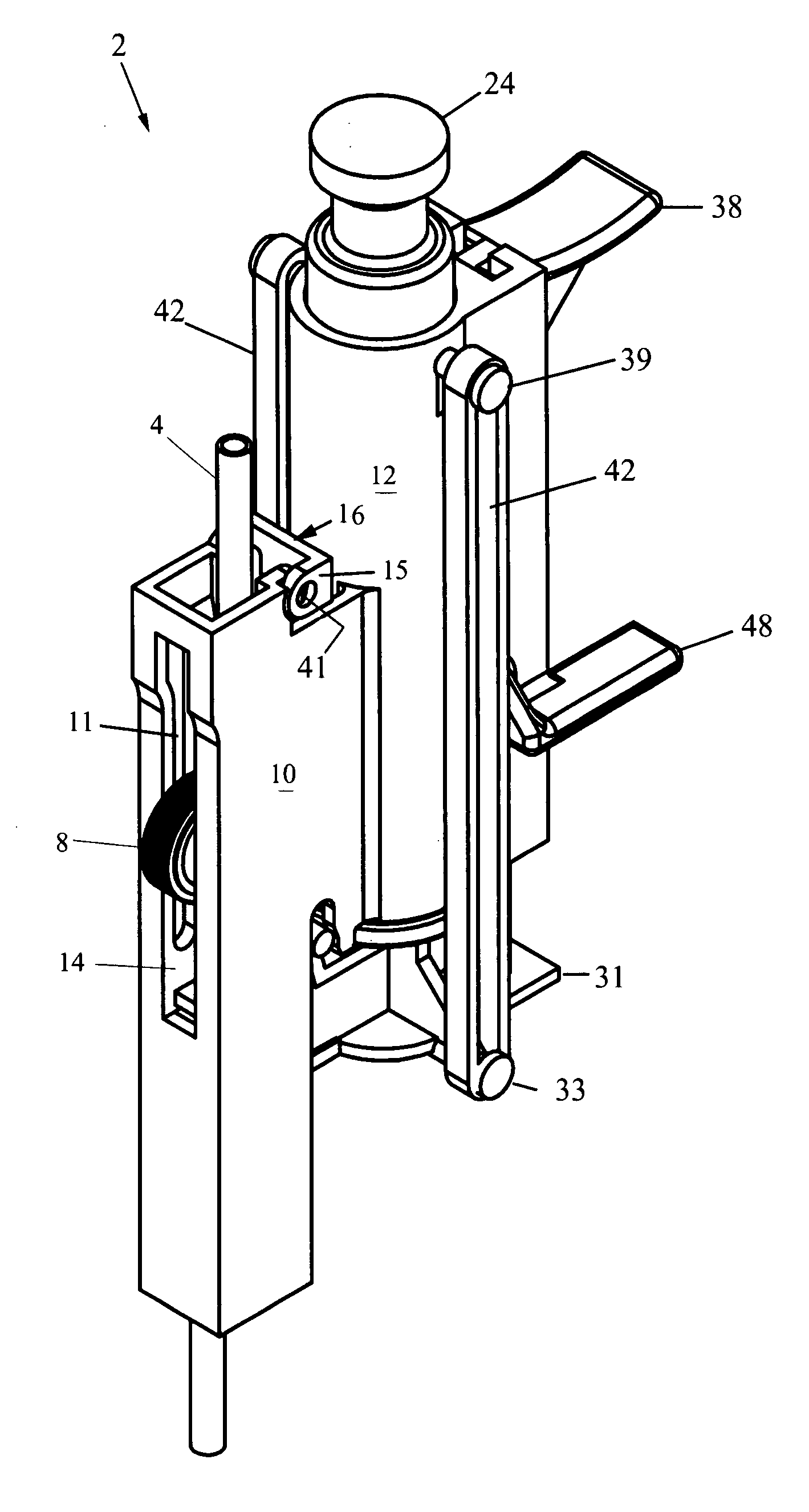
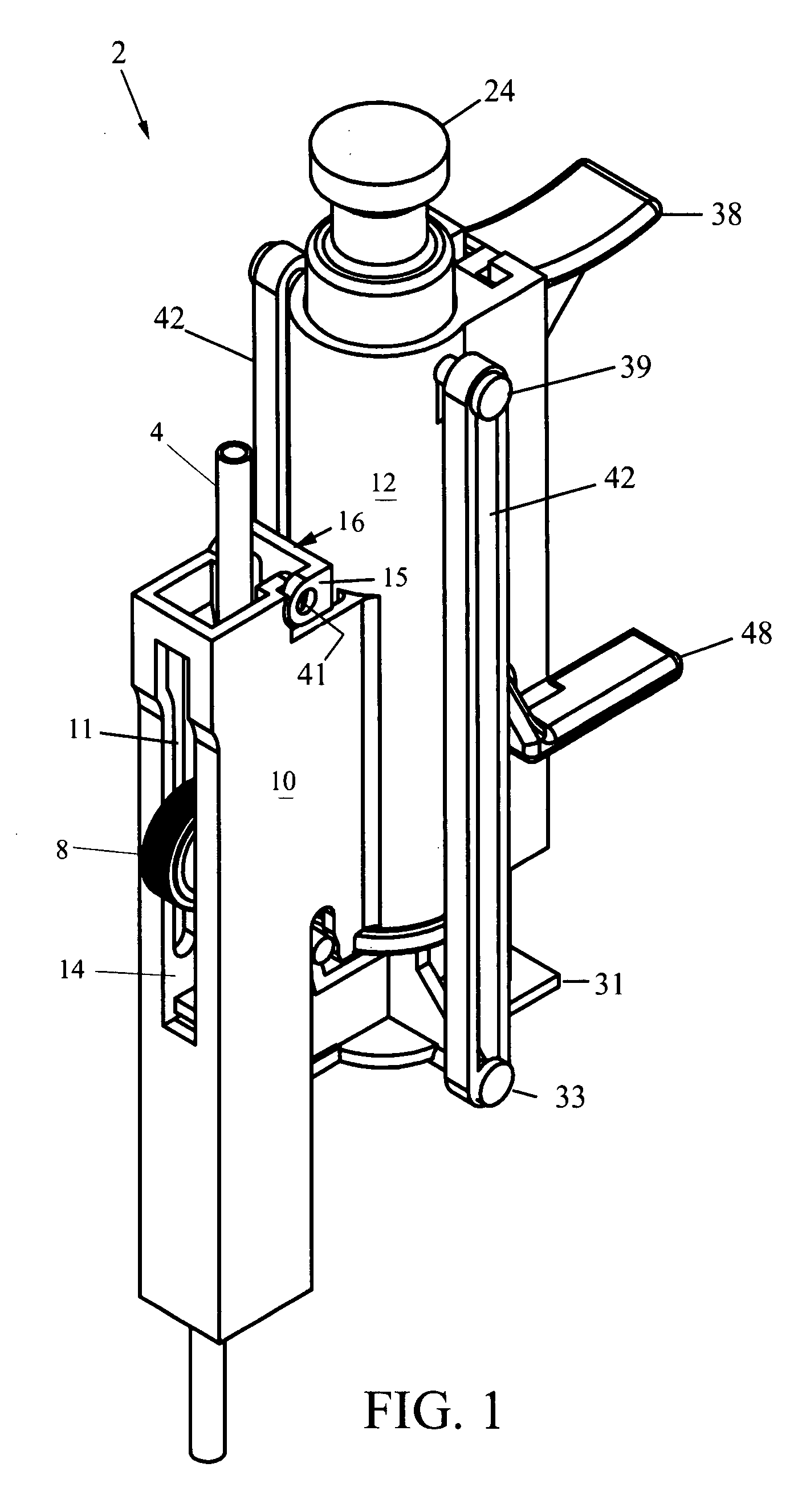
[0034]FIG. 1 is a perspective view of a regulator 2 for IV tubing that interrupts normal flow to flush for a specific period of time before returning to pre-flush flow. The regulator 2 generally comprises an elongated housing with main section 10 and a plunger section 12. The main section 10 is formed as a three-walled elongate trough, and the existing IV tubing 4 runs through the trough of main section 10. A roller-clamp 8 is rotatably seated across the trough of the main section 10 and protrudes out of an aperture 14 in the front face of main section 10.

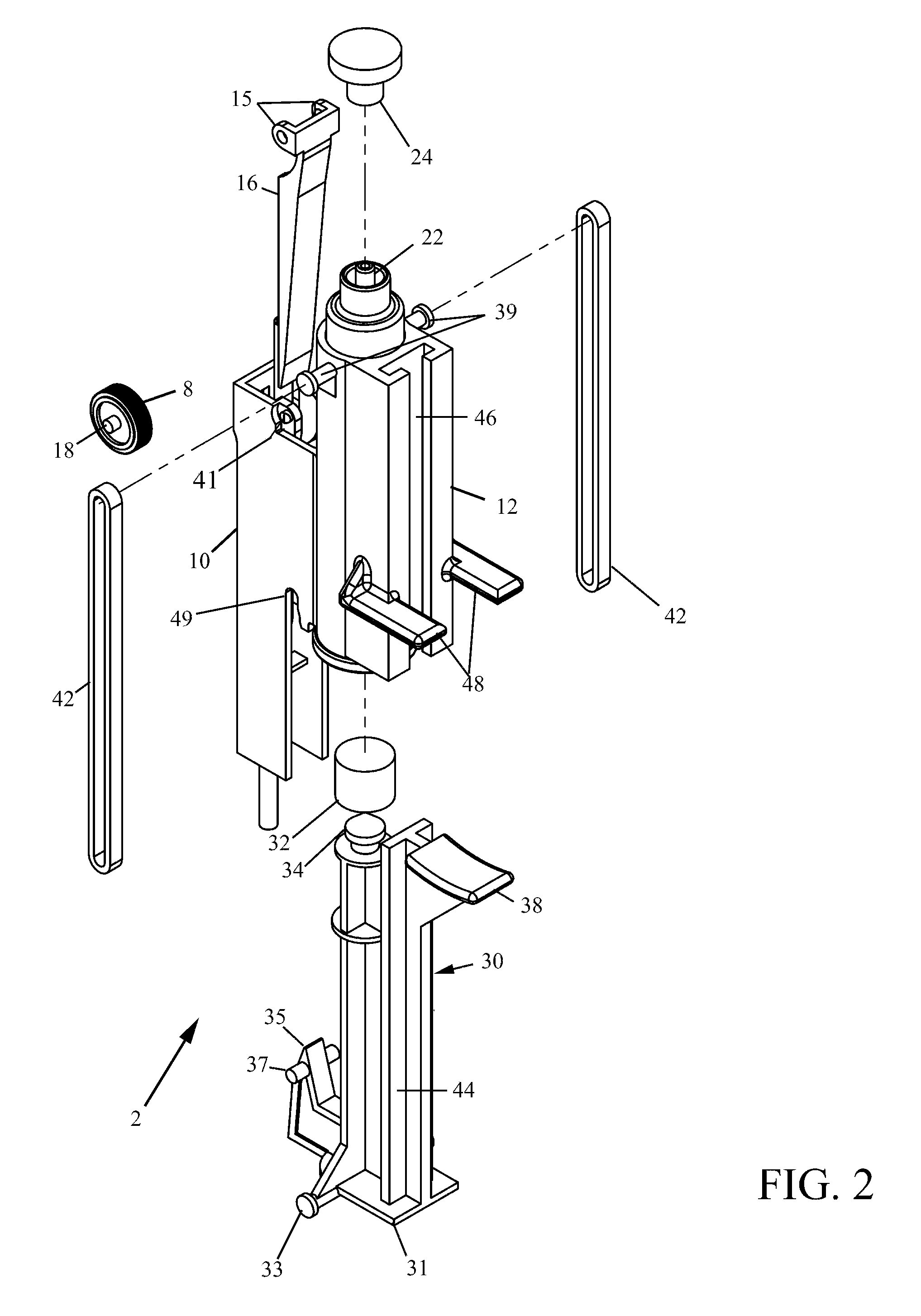
[0035]FIG. 2 is an exploded diagram of the regulator 2 which shows that roller-clamp 8 comprises an annular hub with rubber tread mounted thereon, and opposing posts 18 forming an axle. These posts 18 of the roller-clamp 8 are carried in vertical notches 11 formed inside the trough of the main section 10, and the roller-clamp 8 is free to slide up and down along the notches 11 within the trough of the main section 10. In operation...

second embodiment

[0044]FIG. 5 is a perspective view of a regulator 102 for IV tubing 104 that interrupts normal flow to flush for a specific period of time before returning to pre-flush flow. The regulator 102 generally comprises an elongated housing with main section 112 and compressible lever section 114 mounted pivotally thereon. The main section 112 is formed as a trough, and the existing IV tubing 4 runs through the trough of main section 112. A roller-clamp 108 is rotatably seated across the trough of the main section 112 and protrudes out of an aperture 110 in the front face of main section 112.

[0045]As best seen in the side cross-section of FIG. 6 and the front cross-section of FIG. 7, the IV tubing 104 runs internally through the main section over roller-clamp 108. While not explicitly shown, it is necessary to maintain a certain degree of friction between the roller-clamp 108 and the main housing section 112, and between the tubing 104 and the housing. Conventional rubber grommets may be ...


PUM


Abstract

The present invention describes IV regulators that allow interruption of normal controlled-flow for a safe and convenient bolus flush, either for a specific period of time or for a specific volume of saline flush. Two time-controlled IV regulators are shown, one employing a pneumatic cylinder counter-opposed by elastic band(s) for administering a bolus flush, and one employing a compressible lever and torsion spring counter-opposed by a rotary damper. In both cases the mechanisms disengage the roller-clamp from the IV tube for a predetermined amount of time to fully open fluid flow there through for a bolus flush before return to the regulated-flow position. The volume-controlled flow regulator employs two internal bladders and allows one bladder to fill while the other bladder drains (and vice versa) by flipping a slider paddle-type toggle, thus enabling the administration of a set volume of flush fluid.

Description

CROSS-REFERENCE TO RELATED APPLICATION(S)[0001]The present application derives priority from U.S. provisional application Ser. No. 60 / 851,856 filed 13 Oct. 2006.BACKGROUND OF THE INVENTION[0002]1. Field of the Invention[0003]The present invention relates to flow regulators for intravenous (IV) equipment and, more particularly, to a manually-operated regulator that allows interruption of normal controlled-flow for a safe and convenient bolus flush (full flow of saline for a specific period of time or volume of flush) before returning to a “pre-flush” flow setting, eliminating the need to manually reset the roller regulator or to administer a separate saline flush.[0004]2. Description of the Background[0005]Intravascular or IV sets deliver fluid, medications, blood products and parenteral nutrition to patients. Most IV machines operate by gravity or by an infusion pump (a pump, usually peristaltic, used to control the flow through the IV tube). FIG. 14 is a perspective view of a conve...

Claims


Application Information

Patent Timeline
Patent Type & Authority Patents(United States)
IPC IPC(8): A61M5/00A61M5/14
CPCA61M5/16809A61M5/16813A61M39/286A61M2005/1403A61M2205/583
Inventor MURPHY, TODDKLASSEN, CHRISTOPHERSCHNEIDER, ERICLIPFORD, BRIAN LEE
Owner MURPHY TODD
Why Eureka
Try Eureka