
Rainwater Collection and Redistribution System

Inactive Publication Date: 2011-01-13
HARRINGTON JIM
View PDF12 Cites 20 Cited by
  • Summary
  • Abstract
  • Description
  • Claims
  • Application Information

AI Technical Summary

Benefits of technology

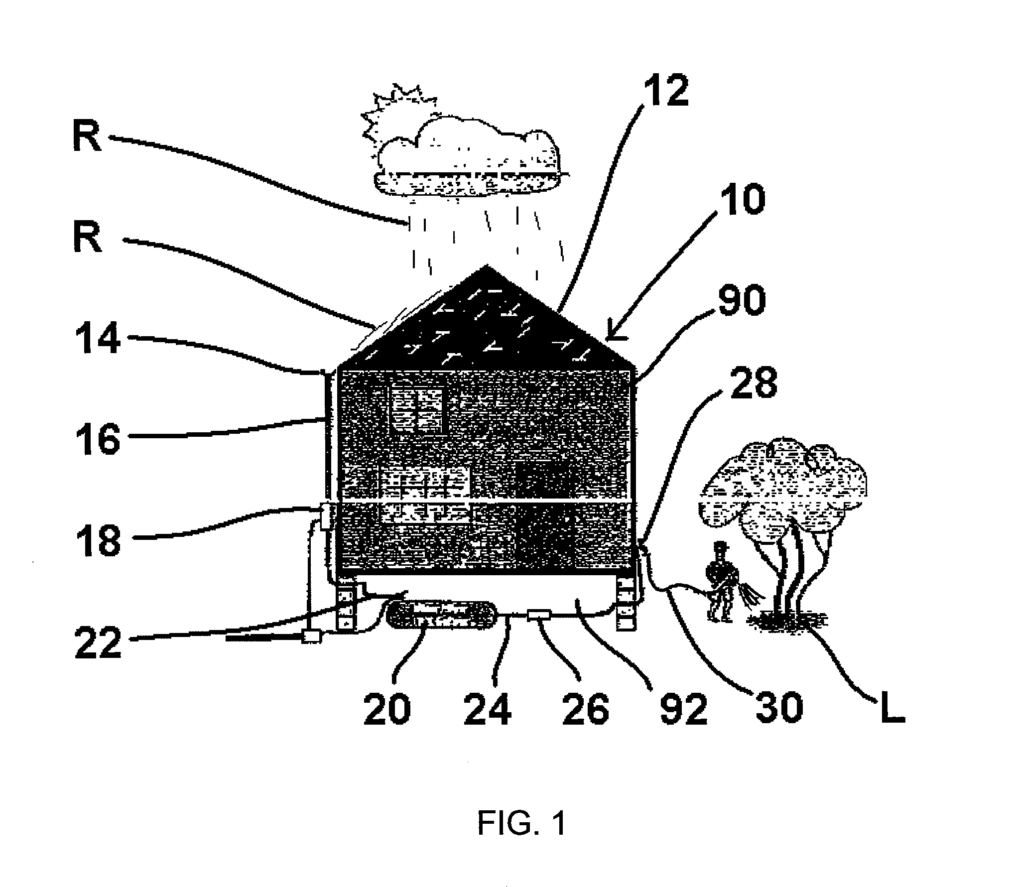
[0012]The system and method utilizes a conventional roof and guttering system to catch rainwater and direct the rainwater into a storage or collection vessel. Rainwater falls onto the conventional roof and flows into the guttering system where it is directed to downspouts or down pipes. The downspouts direct the rainwater to a collection vessel, which can be a flexible polyvinylchloride, or other suitable polymer or other material, structure, for storing the rainwater for later use. The collection vessel has an outlet that preferably is connected to a pump for pumping the rainwater out of the collection vessel for use. A hose or other means for redistributing the rainwater can be connected to the pump for redistributing the rainwater in, for example, a garden or to other landscape features. Thus, rainwater can be collected and stored for later use, saving on the cost of purchasing water from a public source, and conserving water.
[0013]Preferably, the collection vessel is located under the home, such as in a crawl space under the home if the home does not have a basement and is not built on a slab. Alternatively, the collection vessel can be located proximal to the home, especially if the home has a basement or is built on a slab. By locating the collection vessel proximal to the home, and therefore proximal to the guttering system, the need for additional piping to direct the rainwater from the downspouts to the collection vessel is reduced.
[0015]The water filter also can include an overflow drain between the filter inlet and the collection vessel to prevent a water back up in the guttering system, which could lead to water infiltrating the home, water ponding under the home, water damage to the home, and erosion of landscaping proximal to the home. Additionally, the water filter also can include a water shut-off valve to prevent water from entering the collection vessel. Accordingly, the water filter of the present invention may selectively route the water from the filtration reservoir to the collection vessel for collection and later use, or to the overflow drain for normal disposal on the ground, or to a rainwater drainage system associated with the property.
[0017]The invention also can comprise convenience and safety features. In addition to the filter or filters and the overflow drain between the roof and the collection vessel, it further is convenient and safer to include a drain proximal to the collection vessel to remove overflow or leaking water from proximal to the collection vessel, which often is under the home, to a place away from the home where such water cannot do any damage to the home. Additionally, the inclusion of common shut off valves and the like can make the entire system more convenient and safe.

Problems solved by technology

Such debris can potentially clog the piping of the rainwater collection system and can enter the collection vessel, thus reducing the available volume for rainwater and potentially clogging the functional aspects of the collection vessel, if not removed.

Method used


Image

  • Rainwater Collection and Redistribution System
  • Rainwater Collection and Redistribution System
  • Rainwater Collection and Redistribution System

Examples


Embodiment Construction

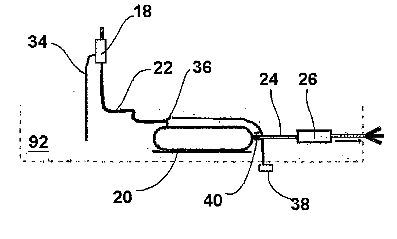
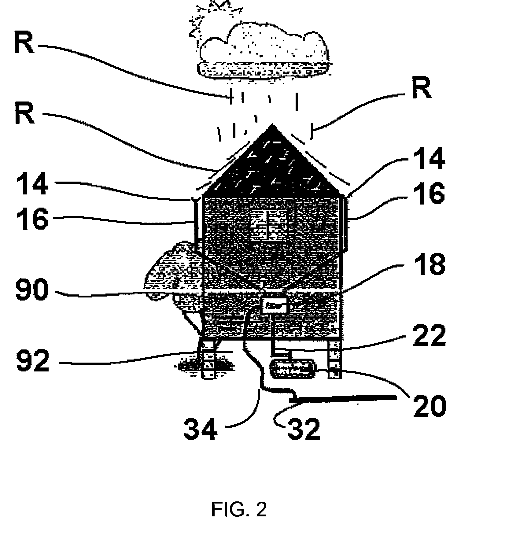
[0027]Referring now to the figures, a rainwater collection and distribution system incorporating preferred embodiments of the invention is shown. FIG. 1 is a side view of a building structure comprising an embodiment of the invention illustrating one manner of attaching the invention to the structure. FIG. 2 is a rear view of a structure comprising an embodiment of the invention. FIG. 3 is a schematic of a rainwater collection system and the preferred elements illustrating the connectivity of the water filter of the present invention. FIG. 4 is a schematic of an embodiment of the collection vessel feature of the invention showing the use of three vessels in series for greater rainwater storage. FIG. 5 is a perspective view illustrating an embodiment of the rainwater filter of the present invention and a rainwater collection vessel. FIG. 6 is a detailed perspective view of a rainwater filter of the present invention. FIG. 7 is a side sectional view of the rainwater filter depicted in...


PUM


Abstract

A system and method for collecting and redistributing rainwater by catching rainwater using a conventional roofing and guttering system, piping the rainwater into a collection vessel for storing the rainwater, pumping the rainwater from the collection vessel through a hose; and redistributing the rainwater from the collection vessel via the hose. The system can comprise a rainwater filter that provides one or more filtration stages to rainwater collected. The rainwater filter has a filter reservoir that includes one or more outlets to communicate filtered water to the collection vessel and one or more overflow ports. The filter may also include a shutoff valve to regulate flow of water into the collection vessel, and a filter reservoir drain to avoid stagnation of water in the filter reservoir.

Description

STATEMENT OF RELATED APPLICATIONS[0001]This patent application is based on and claims the benefit of U.S. provisional patent application No. 60 / 991,230 having a filing date of 30 Nov. 2007 and U.S. provisional patent application No. 61 / 097,607 having a filing date of 17 Sep. 2008, both of which are incorporated herein in their entireties by this reference.BACKGROUND OF THE INVENTION[0002]1. Technical Field[0003]The present invention generally relates to systems for collecting and redistributing rainwater and to systems for collecting rainwater from conventional roofing and guttering systems into a water collection storage vessel for later redistribution such as for landscaping uses. The present invention further relates to a water filter used in connection with the rainwater collection and redistribution systems.[0004]2. Prior Art[0005]As the extreme drought in the southeastern United States in 2007 has reinforced to residents of the United States, water is a very precious commodity...

Claims


Application Information

Patent Timeline
IPC IPC(8): E03B3/00
CPCE03B1/04E04D2013/086E03B2001/047Y10T137/0318Y10T137/6969Y02A20/108
Inventor HARRINGTON, JIM
Owner HARRINGTON JIM
Learn More