
Wheel brake mechanism for a baby stroller

a technology of brake device and wheel, which is applied in the direction of hand cart accessories, carriage/perambulator accessories, hand carts, etc., can solve the problems of stroller losing its balance, baby falling out of the stroller, and the inability to operate the brake mechanism simultaneously, so as to avoid the damage to the surface of the user's shoes during the operation of the brake device, and the effect of simple control

Inactive Publication Date: 2008-04-03
GOLDEN POINT MARKETING
View PDF14 Cites 23 Cited by
  • Summary
  • Abstract
  • Description
  • Claims
  • Application Information

AI Technical Summary

Benefits of technology

"The present invention provides an improved brake mechanism for a baby stroller that can be easily operated by stepping on either the front or rear end of a pedal. The brake mechanism includes a pair of connecting elements, a pedal, a transmission shaft, and a pair of sliders. Each connecting element is pivotally connected with a wheel having a toothed portion for detachably engaging with the slider, so as to brake the wheel. Each slider is biased by a resilient element mounted in the connecting element to disengage from the toothed portion of the wheels. The transmission shaft is pivotally connected between the pair of connecting elements and rotatable by the pedal. The brake mechanism can be simultaneously controlled on both sides of the stroller for added safety and convenience."

Problems solved by technology

As the pedals are separately installed on both sides of a stroller, the brake mechanisms cannot be operated simultaneously.
The baby stroller may therefore lose its balance and cause the baby to fall out of the stroller when brake are applied suddenly at a high speed.
In order to control the brake device of the prior art as described above, a user must use the tip of their shoe to hook up the pedal or control plate, which may damage the surface of the user's shoe.

Method used


Image

  • Wheel brake mechanism for a baby stroller
  • Wheel brake mechanism for a baby stroller
  • Wheel brake mechanism for a baby stroller

Examples


Embodiment Construction

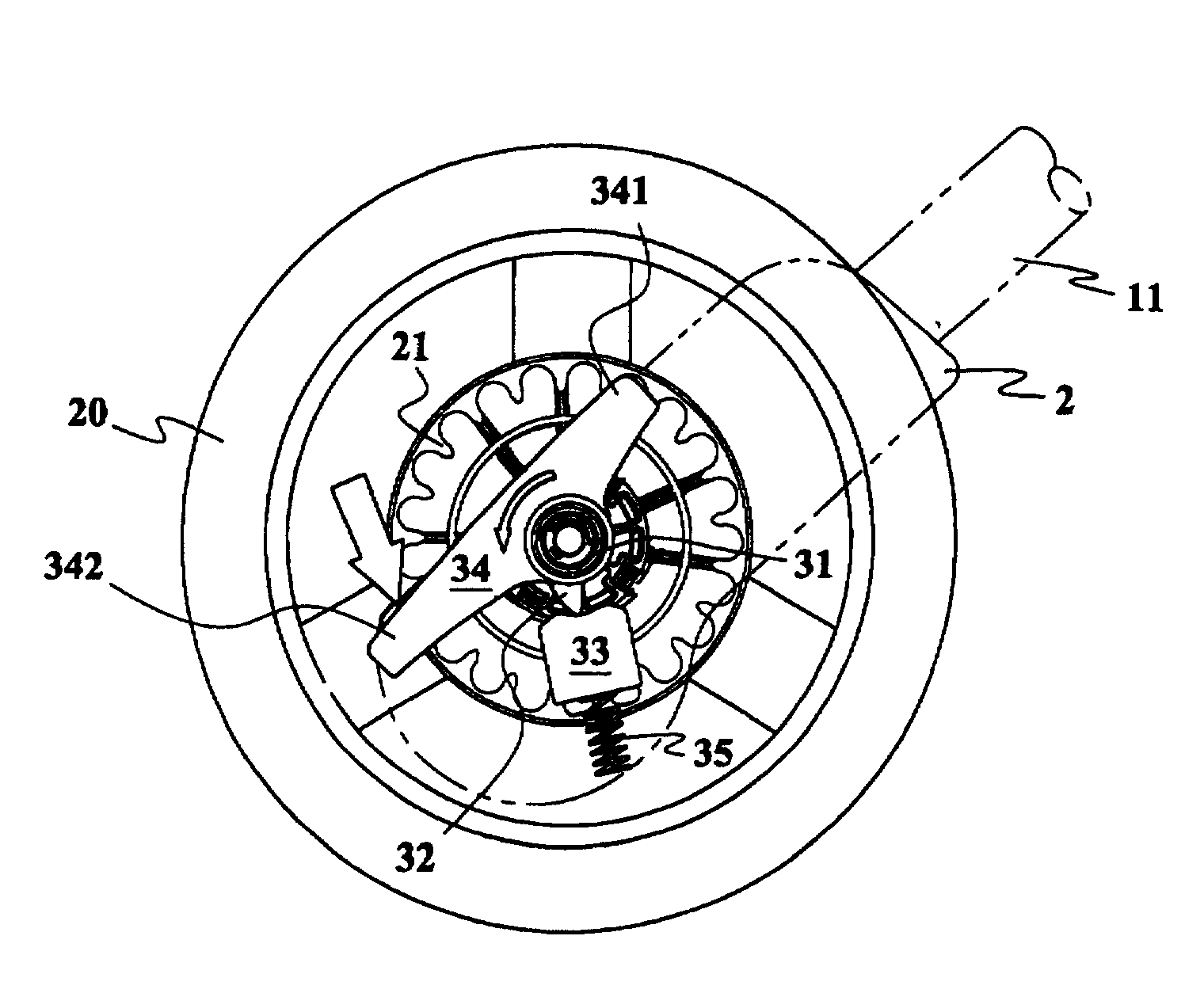
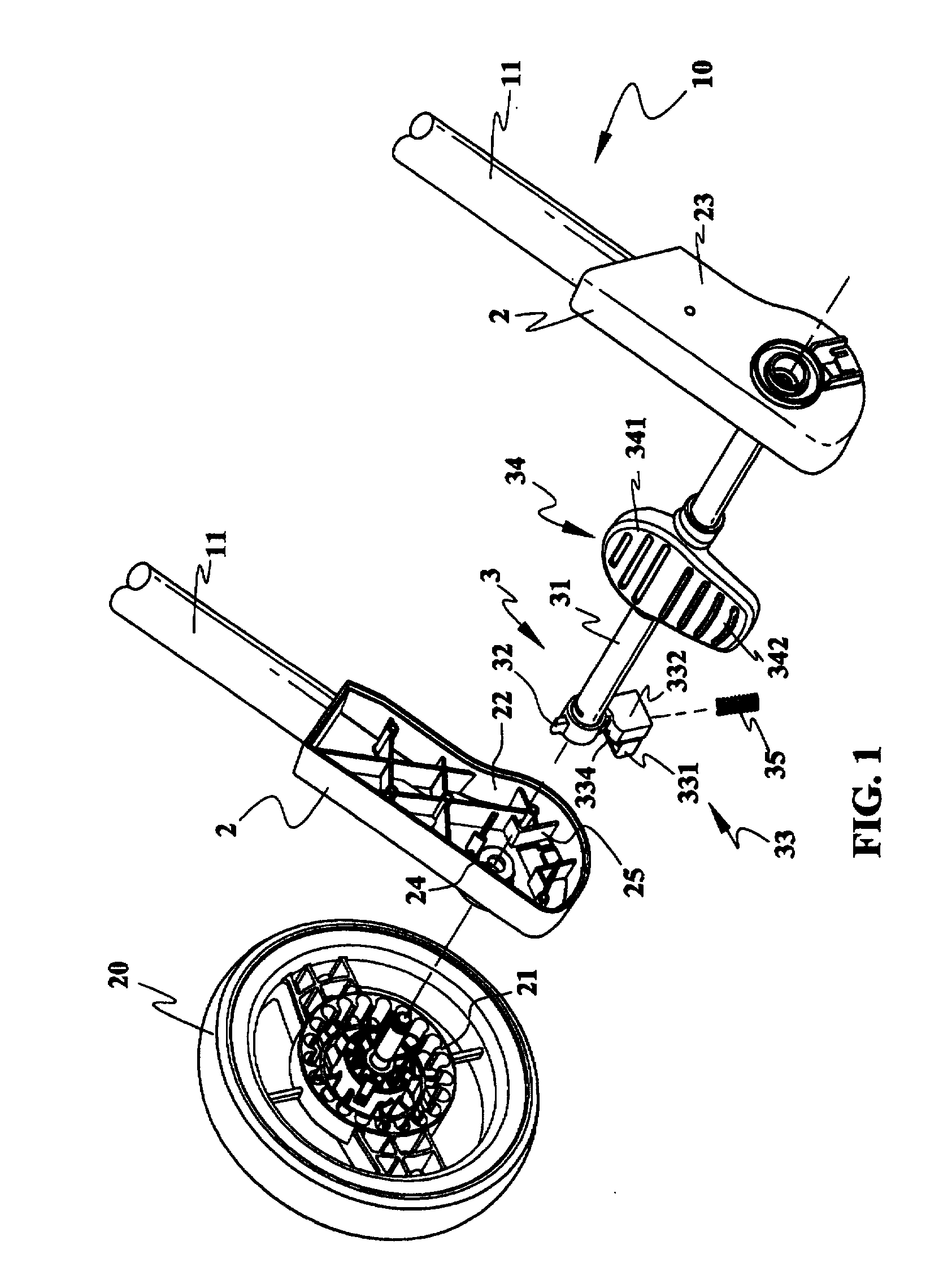
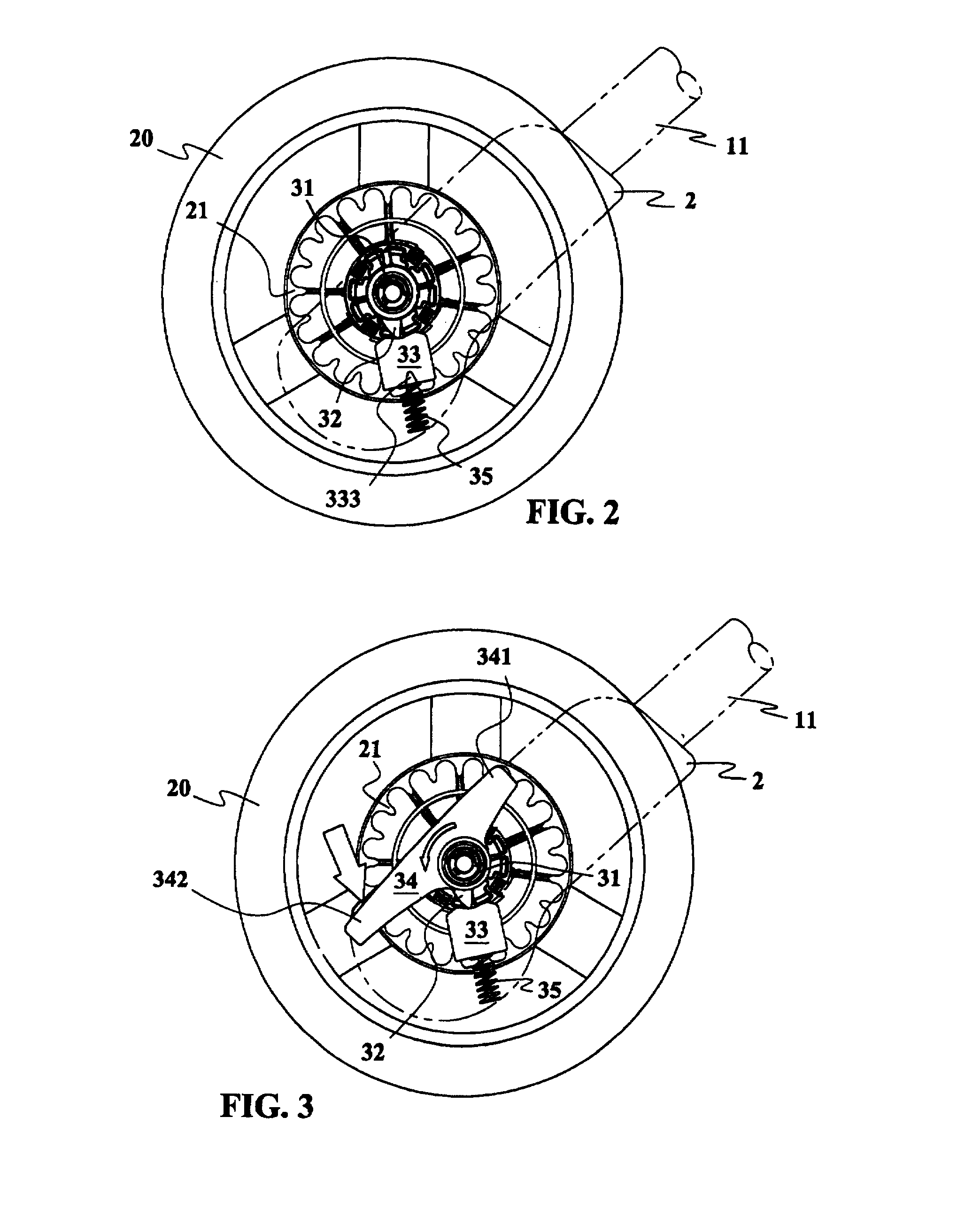
[0022]Referring to FIG. 1, an embodiment of a brake mechanism 3 connects to a pair of rear leg tubes 11 of a stroller frame 10. The brake mechanism 3 includes a pair of connecting elements 2, a pedal 34, a transmission shaft 31 and a pair of sliders 33. Each of the connecting elements 2 is pivotally connected with a wheel 20 which has a toothed portion 21 for detachably engaging with the slider 33 to brake the wheel 2.

[0023]The pair of connecting elements 2 are connected to the rear leg tubes 11 respectively at the top end thereof. Each connecting element 2 has a wall 23 which is formed with an inner space 22, a axle hole 24, and a guiding slot 25. The wheel 20 is pivotally installed on the axle hole 24. The slider 33 is slidably received within the guiding slot 25. Further, the inner space 22 is installed with a resilient element 35 for biasing the slider 33 to disengage from the toothed portion 21 of the wheel 20.

[0024]The pedal 34 is connected to the transmission shaft 31 and has...


PUM


Abstract

A wheel brake mechanism for a baby stroller has a pair of sliders which can be released from and engaged with a toothed portion of a pair of rear wheels. The pair of sliders are driven by a pedal via a transmission shaft. The pedal has a rear end and a front end. A user may step downwardly on the rear end of the pedal to simultaneously brake the rear wheels on either side of the stroller; and step on the front end of the pedal to simultaneously release the rear wheels from a braked state.

Description

FIELD OF THE INVENTION[0001]The present invention relates to a brake mechanism for a baby stroller and in particular, to a brake mechanism with a pedal which is operable in either a front direction or a rear direction.DESCRIPTION OF THE RELATED ART[0002]There are many mechanisms and methods being used commercially for braking a baby stroller. The basic type of mechanism is furnished with a pedal having a toothed portion operatively connected to a rear wheel. The rear wheel also has an engageable toothed portion for detachably engaging with the toothed portion of the pedal, in order to brake the stroller.[0003]As the pedals are separately installed on both sides of a stroller, the brake mechanisms cannot be operated simultaneously. The baby stroller may therefore lose its balance and cause the baby to fall out of the stroller when brake are applied suddenly at a high speed.[0004]For fast movement of a baby stroller or a jogger on a steep or rugged road, it is preferable to brake the ...

Claims


Application Information

Patent Timeline
Patent Type & Authority Applications(United States)
IPC IPC(8): B62B9/08
CPCB62B5/0433B62B9/087B62B9/082B62B5/0461
Inventor YEH, PO-SHIUNG
Owner GOLDEN POINT MARKETING
Learn More