Decorative windmill with solar panel

a solar panel and windmill technology, applied in wind motors with solar radiation, electric generator control, greenhouse gas reduction, etc., can solve the problems of user injury, safety risks involved in the use of current windmill designs, and not fully enjoying the decorative elements of windmills, etc., to achieve a convenient and convenient windmill

Inactive Publication Date: 2008-03-18
LAKESOUTH HLDG LLC
View PDF12 Cites 19 Cited by
  • Summary
  • Abstract
  • Description
  • Claims
  • Application Information

AI Technical Summary

Benefits of technology

[0009]Therefore, it is an object of the present invention to provide a safer and more convenient windmill system, having features allowing the user to easily utilize the system.
[0010]This object is achieved by providing a safer and more convenient windmill which allows the user to easily implement and utilize the system.
[0011]The present invention provides significant advantages, including: (1) allowing visual inspection of the windmill when the windmill is located in a poorly illuminated space thereby reducing the risk of physical injury related to using the windmill, such as stumbling due to poor illumination; (2) providing electrical power to electrical devices associated with windmill use or the decoration of a windmill; and (3) providing a convenient structure from which windmill accessories may be hung.

Problems solved by technology

For example, some decorative windmills are used outdoors at night when the user of the windmill may not be able to visually inspect the windmill, thereby not fully enjoying the decorative elements of the windmill.
Also, safety risks are involved with the use of current windmill designs.
For example, a poorly illuminated windmill could easily be the cause of a user to stumble or otherwise incur physical injury due to lack of illumination.
One problem with these common designs is that the windmills do not offer a convenient structure from which to hang accessories associated with decorative windmill.

Method used


Image

  • Decorative windmill with solar panel
  • Decorative windmill with solar panel
  • Decorative windmill with solar panel

Examples


Embodiment Construction

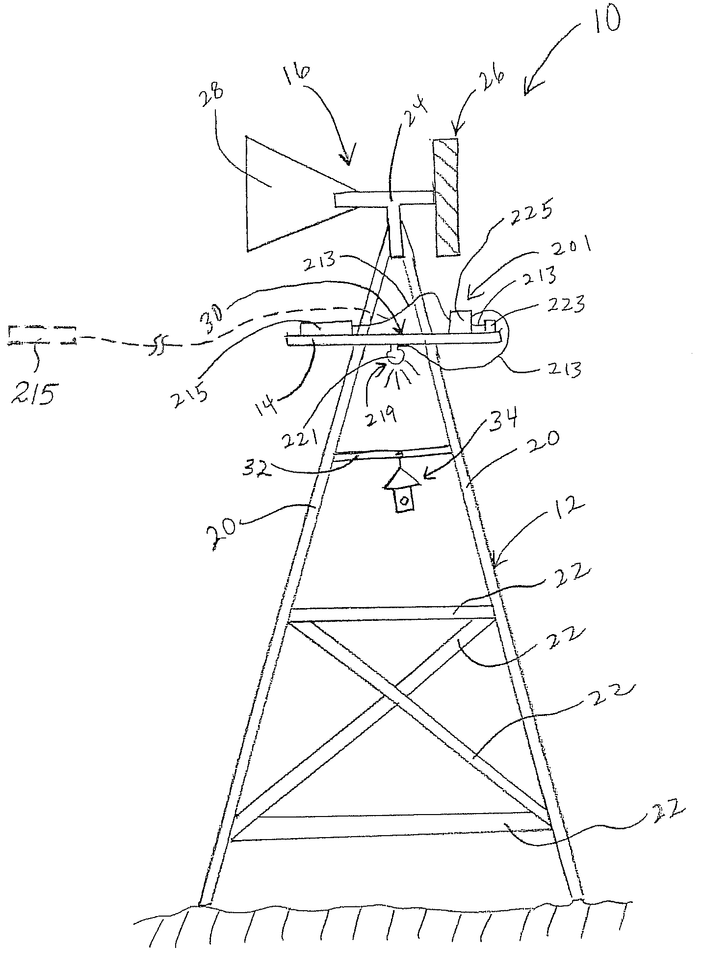
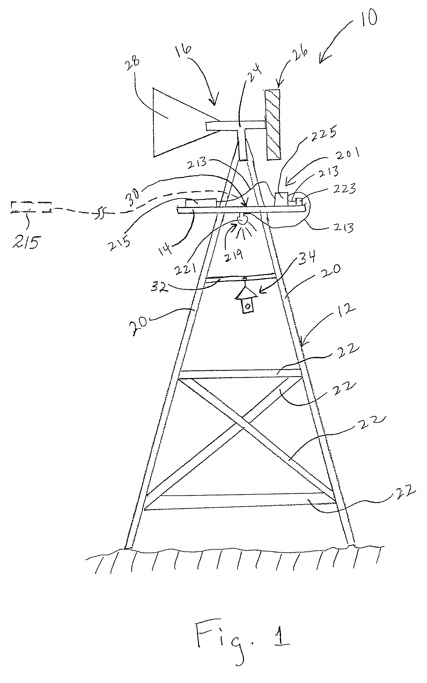
[0019]Referring now to FIG. 1 in the drawings, the preferred embodiment of a windmill system 10 according to the present invention is illustrated. Windmill system 10 preferably comprises a frame 12, a platform 14, a wind assembly 16, and a solar energy system 201. Frame 12 preferably comprises a plurality of legs 20 and a plurality of cross members 22. Wind assembly 16 preferably comprises a swivel bracket 24, a blade assembly 26, and a vane 28.

[0020]Legs 20 and cross members 22 are preferably connected to substantially form a four sided standing structure. It should be appreciated that alternate embodiments of frame 12 may have more or fewer than four sides. Legs 20 substantially converge toward each other at the top end of legs 20. Platform 14 is connected to and carried by frame 12. Platform 14 is preferably a thin rectangular plate-like structure with a hole for accommodating the nearly converged ends of legs 20 therethrough.

[0021]Wind assembly 16 is preferably attached to the t...


PUM


Abstract

A decorative windmill having a solar energy system for powering an electrical subsystem is disclosed. The electrical subsystem may include lighting elements for illuminating the windmill and the area around the windmill in a decorative and functional manner.

Description

[0001]This application claims the benefit of U.S. Provisional Application No. 60 / 656,577, filed 25 Feb. 2005, titled “SOLAR POWERED WINDMILL.”BACKGROUND OF THE INVENTION[0002]1. Field of the Invention[0003]The present invention relates in general to the field of decorative windmills.[0004]2. Description of Related Art[0005]There are many designs of decorative windmills well known in the art. However, there remains room for improvement upon current decorative windmill designs. There are many occasions on which a user needs electrical energy to power devices for use in association with decorative windmills. For example, some decorative windmills are used outdoors at night when the user of the windmill may not be able to visually inspect the windmill, thereby not fully enjoying the decorative elements of the windmill. Also, safety risks are involved with the use of current windmill designs. For example, a poorly illuminated windmill could easily be the cause of a user to stumble or oth...

Claims


Application Information

Patent Timeline
Patent Type & Authority Patents(United States)
IPC IPC(8): F03D9/00
CPCF03D9/007F05B2220/25Y02E10/72F03D9/11F03D9/25F03D13/20F03D80/00Y02E70/30
Inventor JONES, CHAD H.PLASEK, SCOTT A.KUELBS, GUSTAV P.
Owner LAKESOUTH HLDG LLC
Why Eureka
Try Eureka