Three wavelength quantitative imaging systems

a quantitative imaging and three-wavelength technology, applied in the field of optical systems, can solve the problems of incompatibility with human perception of time, high precision of contact methods, and high computational intensity of processes, and achieve the effect of reducing or eliminating undesired optical signals

Inactive Publication Date: 2011-07-12
UT BATTELLE LLC
View PDF7 Cites 9 Cited by
  • Summary
  • Abstract
  • Description
  • Claims
  • Application Information

AI Technical Summary

Benefits of technology

[0008]An optical system includes more than two optical interferometers that generate interference phenomena between optical waves to measure a plurality of distances, a plurality of thicknesses, and a plurality of indices of refraction of a sample. An electromagnetic detector receives an output of the optical interferometers to render a magnified image of at least a portion of the sample. A controller reduces or eliminates undesired optical signals through a hierarchical phase unwrapping of the output of the electromagnetic detector.

Problems solved by technology

Some scanning and contact methods provide high precision measurements but at very slow speed.
These processes may be computationally intensive, may not match a human's perception of time (e.g., real-time), and may introduce unwanted interference or noise.

Method used


Image

  • Three wavelength quantitative imaging systems
  • Three wavelength quantitative imaging systems
  • Three wavelength quantitative imaging systems

Examples


Embodiment Construction

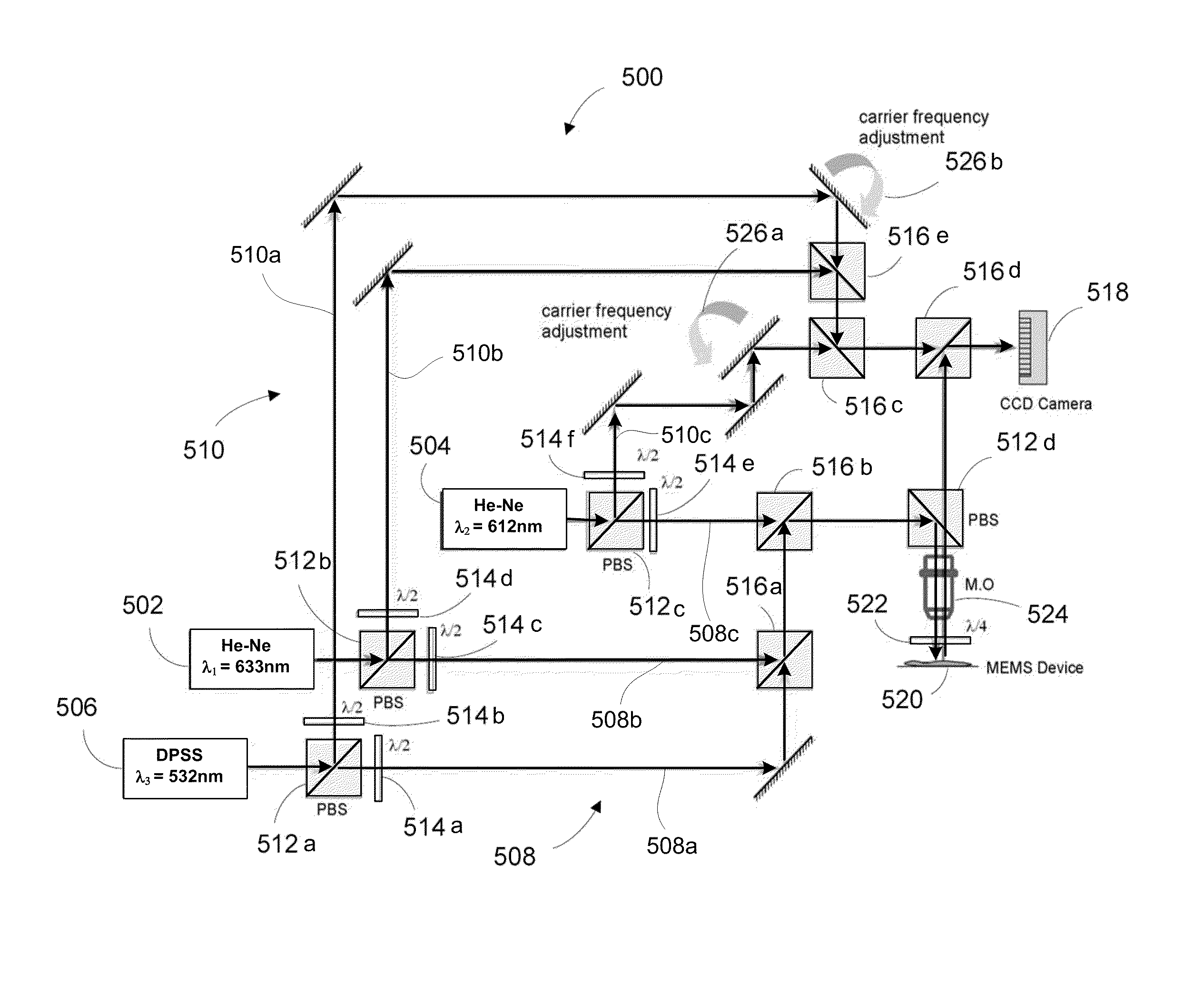
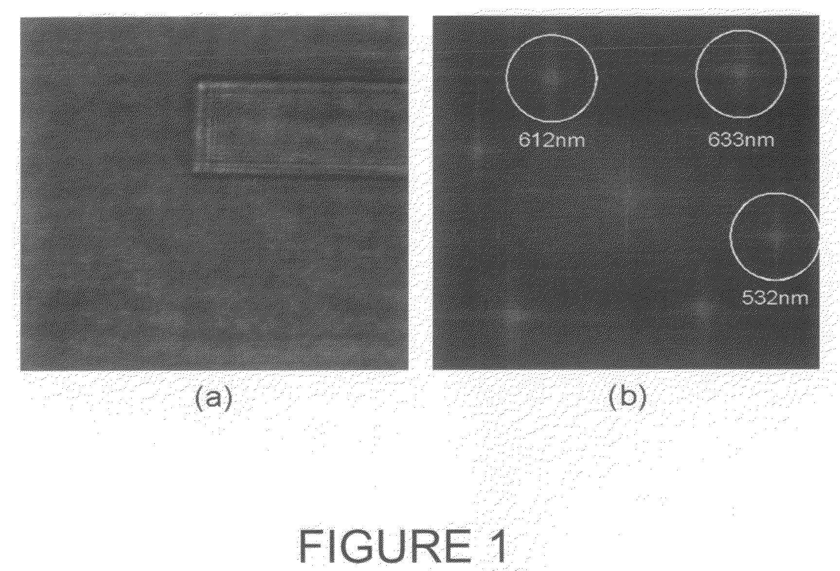
[0019]An optical system may reproduce three-dimensional visual images by recording light interference patterns on a recording medium. The system may measure quantitative phase information that may detect height changes of a few nanometers or less, render distinct image clarity in real-time through a numerical focus, and may capture a large depth of field in a single image (e.g., a single shot).

[0020]The optical system may include three or more digital optical interferometers that may not require multiple image acquisitions through a sequence of illuminating projections. When reconstructed, the images may provide high resolution data that may establish length, width, and / or depth information while suppressing distortion that may occur during signal capture. The phase information may establish a refractive index and / or optical thickness of an object or sample. The data captured may be retained within a local or a remote memory or database that facilitates real-time imaging and viewing...


PUM

PropertyMeasurementUnit
speedsaaaaaaaaaa
speedsaaaaaaaaaa
frequencyaaaaaaaaaa

Abstract

An optical system includes more than two optical interferometers that generate interference phenomena between optical waves to measure a plurality of distances, a plurality of thicknesses, and a plurality of indices of refraction of a sample. An electromagnetic detector receives an output of the optical interferometers to render a magnified image of at least a portion of the sample. A controller reduces or eliminates undesired optical signals through a hierarchical phase unwrapping of the output of the electromagnetic detector.

Description

BACKGROUND OF THE INVENTION[0001]1. Related Application[0002]This application is related to U.S. application Ser. No. 12 / 405,063 filed on Mar. 16, 2009, entitled “Quantitative Phase-Imaging Systems” and U.S. application Ser. No. 12 / 405,089 filed on Mar. 16, 2009, entitled “Quantitative Phase-Contrast and Excitation-Emission Systems” which are incorporated by reference.[0003]2. Technical Field[0004]This disclosure relates to optical systems and particularly to systems that generate three-dimensional visual images while suppressing undesired signals.[0005]3. Related Art[0006]Processes that determine position on or within an object may monitor other systems. Research and manufacturing are becoming reliant on some processes that make high-speed, precise shape and deformation measurements. Some scanning and contact methods provide high precision measurements but at very slow speed.[0007]When optical devices are used, surface features may be magnified by phase unwrapping processes. These ...

Claims


Application Information

Patent Timeline
Patent Type & Authority Patents(United States)
IPC IPC(8): G01B9/02G01N21/41G01N21/43G01B11/02
CPCG01B9/021G01B11/0675G01B11/2441G03H1/0443G03H1/0866G03H2001/0038G03H2001/0456G03H2001/0875G03H2222/13
Inventor MANN, CHRISTOPHER J.BINGHAM, PHILIP R.
Owner UT BATTELLE LLC
Why Eureka
Try Eureka