Ophthalmic lens element

a technology of ophthalmology and lens elements, applied in the field of ophthalmology lens elements, can solve the problems of hyperopic foveal blur, eye cannot properly focus near objects on the retina, and the eye cannot properly focus distant objects on the retina

Active Publication Date: 2011-08-09
CARL ZEISS VISION AUSTRALIA HO
View PDF11 Cites 49 Cited by
  • Summary
  • Abstract
  • Description
  • Claims
  • Application Information

AI Technical Summary

Benefits of technology

[0011]In general terms, the present invention provides an ophthalmic lens element that exhibits a relative plus power throughout a peripheral region of the lens as compared to a central region, and a distribution of power and surface astigmatism which provides clear distance vision in the central region and clear near vision in an area of the peripheral region that is likely to be used for a wearer's near vision tasks.
[0012]The distribution of relative plus power throughout the peripheral region provides an optical correction for retarding or arresting myopia for a wearer. In use, the provision of the relative plus power throughout the peripheral region provides a “stop signal” around substantially the whole of the periphery of the wearer's retina and is thus likely to be more effective on retarding or arresting progression of myopia compared to ophthalmic lens elements that provide a required stimulus of plus power only in a lower part of the lens element.
[0013]The peripheral region includes a region, in the form of a lower or near viewing zone, suitable for the wearer's near vision tasks and which is connected to an upper or distance viewing zone in the central region via a corridor of low astigmatism. The provision of the corridor and the near viewing zone may reduce the need for a lens wearer to tilt their head when reading and thus makes the lens more comfortable to wear.

Problems solved by technology

If an eyeball is “too long” relative to its “on-axis” focal length (meaning, the focal length along the optical axis of the eye), or if the outside surface (that is, the cornea) of the eye is too curved, the eye will be unable to properly focus distant objects on the retina.
Similarly, an eyeball that is “too short” relative to its on-axis focal length, or that has an outside surface which is too flat, will be unable to properly focus near objects on the retina.
Prolonged reading has been suspected of causing a hyperopic foveal blur due to insufficient accommodation.
The therapeutic benefit of these lenses in clinical trials has been shown to be statistically significant in retarding progression of myopia but clinical significance appears to be limited (e.g., Gwiazda et al., 2003, Invest. Opthalmol. Vis. Sci., Vol. 44, pp.
424-430, have found that accommodation also increases the relative peripheral refractive error, possibly due to the increased choroidal tension during accommodation pulling the peripheral retina inward.
Unfortunately, conventional myopia correcting lenses haphazardly produce clear or defocused images in the retina's peripheral region.
Thus, existing ophthalmic lenses for correcting myopia may fail to remove stimuli for myopia progression.

Method used


Image

  • Ophthalmic lens element
  • Ophthalmic lens element
  • Ophthalmic lens element

Examples


Embodiment Construction

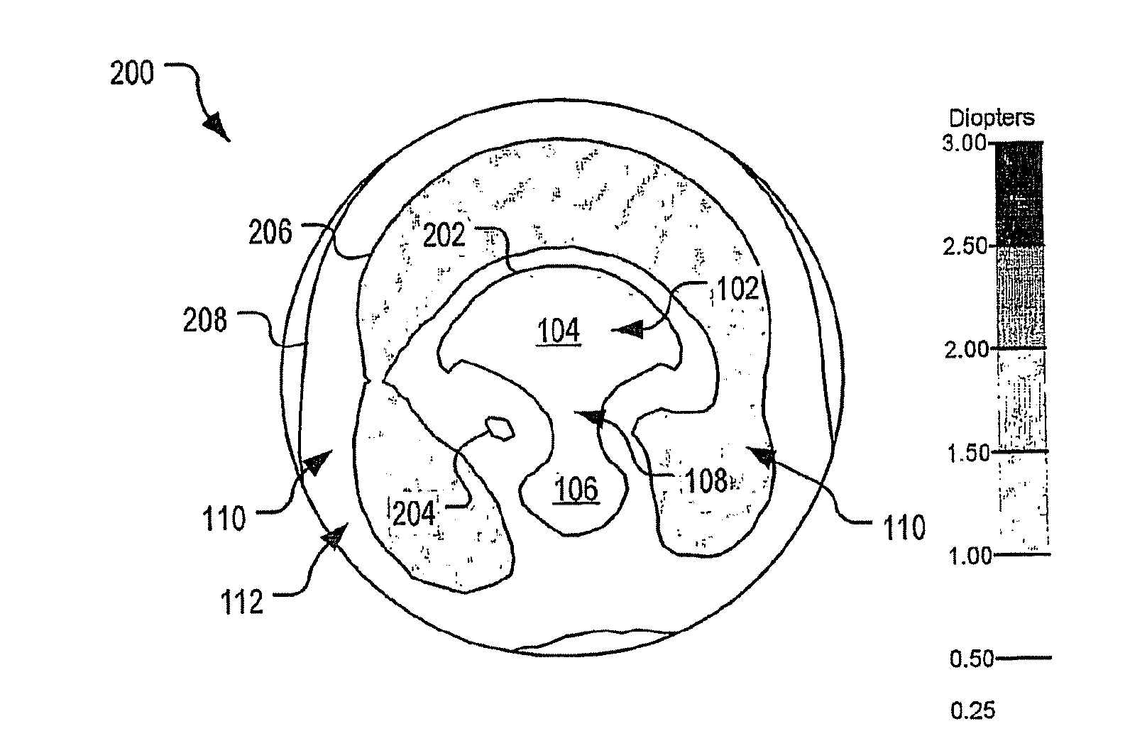
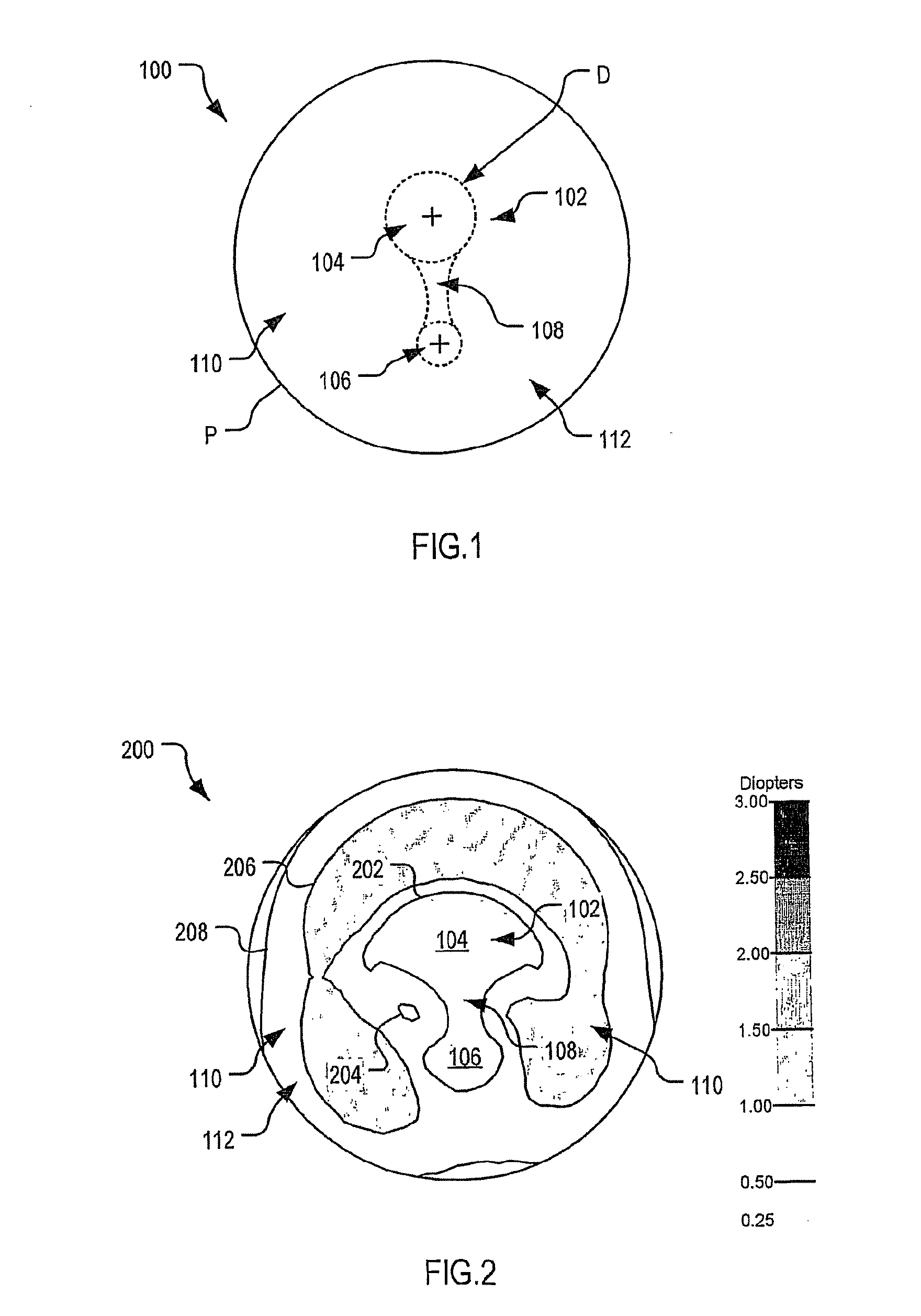
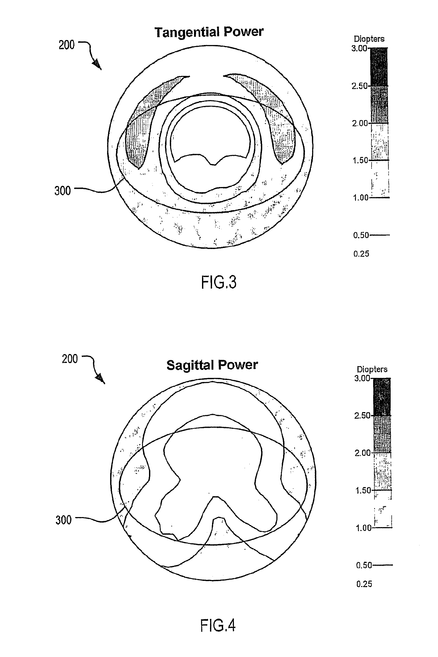
[0124]With reference to FIG. 2 to FIG. 5, an optical lens element 200 according to an embodiment of the present invention was designed having a 3.25 D base curve. In the depicted example, the lens element 200 has a diameter of 60 mm. The contour plots of surface astigmatism, tangential power, sagittal power and mean surface power respectively for the optical lens element 200 are given in FIG. 2 to FIG. 5 respectively. FIG. 3 to FIG. 5 also depict, for reference, a lens overlay 300 representing an example of a lens shape which may be cut from the lens element 200. In the present case, lens overlay 300 represents the outline of a frame measuring 55×35 mm centered 2 mm above the geometric centre of the ophthalmic lens element 200.

[0125]As shown in FIG. 2, the 0.5 D astigmatic contour 202 defines a region of low surface astigmatism including the distance viewing zone 104, the near viewing zone 106, and the corridor 108. The depicted embodiment provides a relatively wide distance viewing...


PUM


Abstract

An ophthalmic lens element is disclosed. The, ophthalmic lens element includes a central region of low surface astigmatism and a peripheral region. The central region includes an upper viewing zone for providing a first power suitable for a wearer's distance vision tasks. The peripheral region has a positive power relative to the first power, and surrounds the central region. The peripheral region provides an optical correction for retarding or arresting myopia for a wearer and includes one or more regions of relatively higher surface astigmatism, a lower or near viewing zone of low surface astigmatism, and a corridor of low surface astigmatism having a surface power varying from that of the upper viewing zone to that of the lower viewing zone. The lower viewing zone is for a wearer's near vision tasks.

Description

[0001]This international patent application claims priority from Australian provisional patent application no. 2006905101 filed on 15 Sep. 2006 and Australian provisional patent application no. 2007901348 filed on 15 Mar. 2007, the contents of each of which are to be taken as incorporated herein by this reference.FIELD OF INVENTION[0002]The present invention relates to ophthalmic lens elements for retarding or arresting myopia, and methods of designing such lens elements.BACKGROUND OF THE INVENTION[0003]To provide focused vision, an eye must be capable of focusing light on the retina. An eye's ability to focus light on the retina depends, to a large extent, on the shape of the eyeball. If an eyeball is “too long” relative to its “on-axis” focal length (meaning, the focal length along the optical axis of the eye), or if the outside surface (that is, the cornea) of the eye is too curved, the eye will be unable to properly focus distant objects on the retina. Similarly, an eyeball that...

Claims


Application Information

Patent Timeline
Patent Type & Authority Patents(United States)
IPC IPC(8): G02C7/06
CPCG02C7/027G02C7/06G02C7/066G02C7/061G02C2202/24G02C2202/08G02C7/04A61F9/00
Inventor VARNAS, SAULIUS RAYMOND
Owner CARL ZEISS VISION AUSTRALIA HO
Why Eureka
Try Eureka