Connector assembly

a technology of connecting parts and connectors, applied in the direction of connections, basic electric elements, electric apparatus, etc., can solve the problem of birdcage strand separation in the cable conductor

Active Publication Date: 2011-08-09
HOXHA VLADIMIR
View PDF26 Cites 18 Cited by
  • Summary
  • Abstract
  • Description
  • Claims
  • Application Information

AI Technical Summary

Problems solved by technology

A disadvantage of this type of wedge connector is that birdcage strand separation in the cable conductor may occur when the wedge is inserted.

Method used


Image

  • Connector assembly
  • Connector assembly
  • Connector assembly

Examples


Embodiment Construction

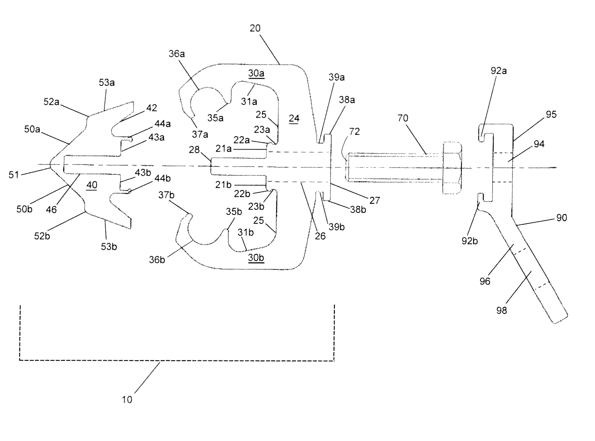
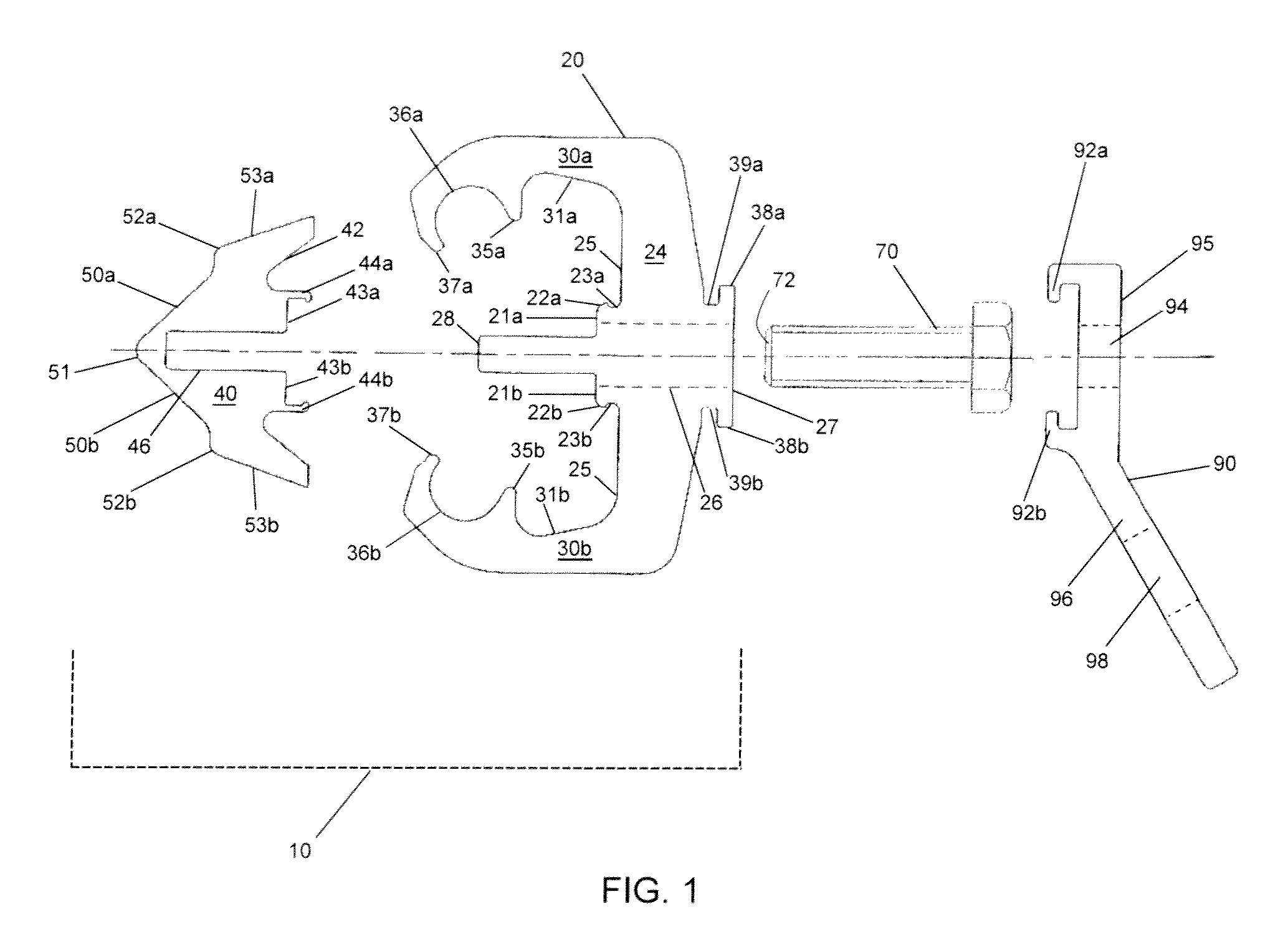
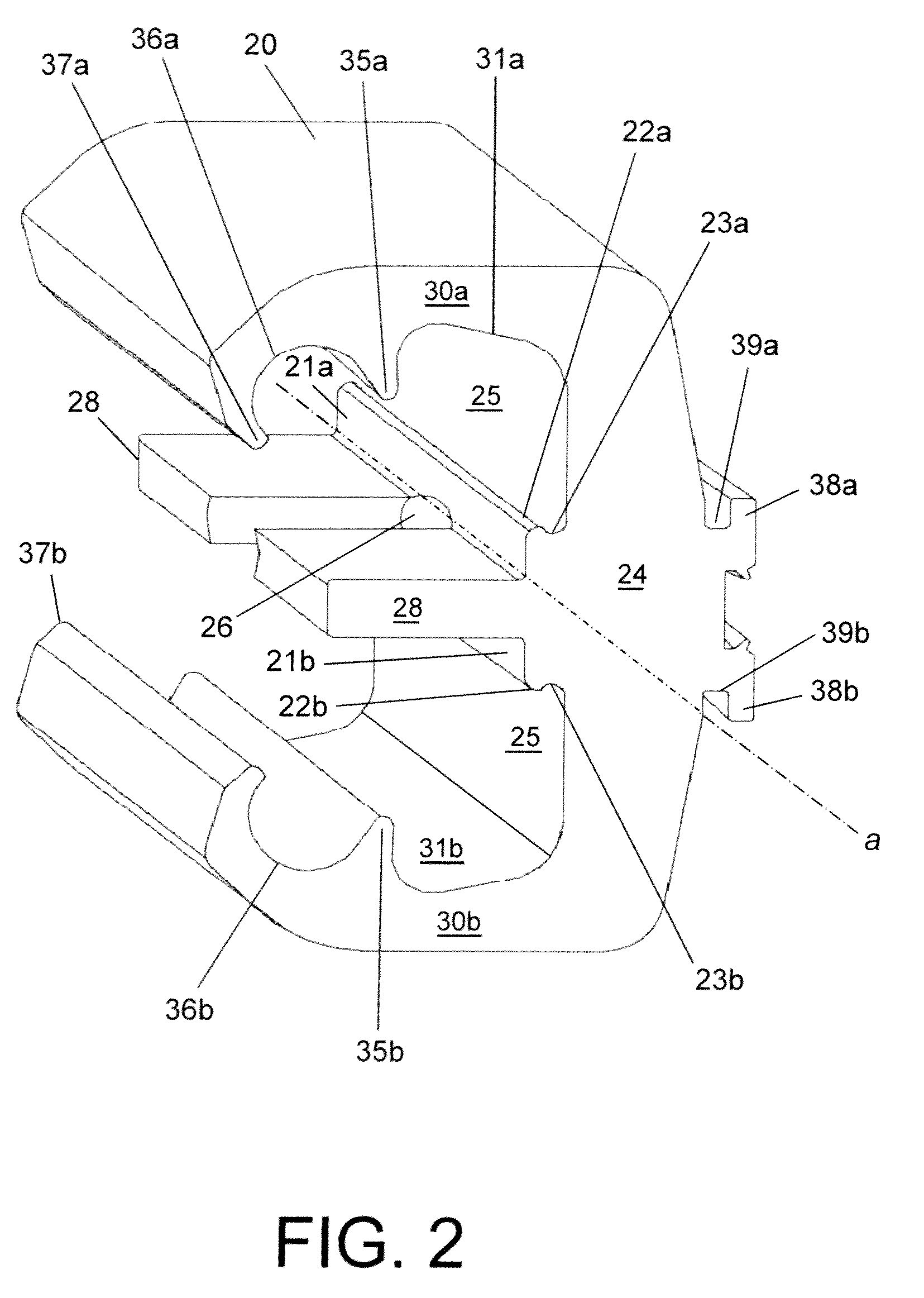
[0018]A connector assembly for joining bare or insulated conductors is provided that has a first member and a second member which cooperate to act as clamps for the conductors. The first member has two beams connected by a body and at least one structural portion for aligning and guiding the first and second members in relation to one another, such as tabs extending from the centre of the body substantially parallel to the two beams. The distal end of the beams, each have a receptacle or channel for receiving a conductor. The second member has two mating faces, each facing a receptacle, and has a body facing surface that complements the shape of the inner surface of the body that it engages, including at least one structural portion adapted to mate with the alignment portion on the first member, such as a groove for receiving the tabs. The second member may be moved by operation of a fastener from an unloaded position, where the second member engages the body, to a loaded position i...


PUM


Abstract

A connector assembly for joining bare or insulated conductors includes a first member and a second member which cooperate to act as clamps. The first member has two beams connected by a body and tabs extending from the center of the body substantially parallel to the two beams. The distal end of the beams each have a receptacle for receiving a conductor. The cross-section of the first member may be Sigma- or E-shaped. The second member has two contact planes, each facing a receptacle, and has a body facing surface that complements the shape of the inner surface of the body that it engages, including a groove for receiving the tabs. The second member is guided by the tabs of the first member when moved by operation of a fastener from an unloaded position, where the second member engages the body, to a loaded position in which the second member is pushed away from the body and holds the conductors securely in place in the receptacles. This connector assembly is adaptable for hot stick applications.

Description

FIELD OF THE INVENTION[0001]The present invention generally relates to electrical tap connectors.BACKGROUND OF THE INVENTION[0002]In electrical power systems, it is often necessary to join two or more conductors in an electrically conductive path. One type of electrical connector for joining conductors such as cables is a wedge tap connector comprising a wedge and a C-shaped member formed of electrically conductive materials. Wedge tap connectors join electrical cables mechanically by forcing a wedge with channels on its opposing sides between a main power conductor and a tap conductor over which is hooked the C-shaped member. The conductors are thereby clamped between the channels in the wedge member and the ends of the C-shaped member. Mechanical fastness is achieved by inserting the wedge between the two cables with sufficient force to cause elasto-plastic deformation of the C-shaped member. A special tool, such as a ram tool actuated by a gunpowder explosion, is therefore typica...

Claims


Application Information

Patent Timeline
Patent Type & Authority Patents(United States)
IPC IPC(8): H01R11/01
CPCH01R4/5091
Inventor HOXHA, VLADIMIR
Owner HOXHA VLADIMIR
Why Eureka
Try Eureka