Mechanically restrained push-on pipe connection

a push-on fitting and mechanical restraint technology, which is applied in the direction of couplings, manufacturing tools, mechanical devices, etc., can solve the problems of difficult control during the insertion action, arduous and time-consuming tasks, and complicated and time-consuming assembly of push-on fittings

Inactive Publication Date: 2011-08-16
SMITH JONES ENTERPRISES
View PDF20 Cites 31 Cited by
  • Summary
  • Abstract
  • Description
  • Claims
  • Application Information

AI Technical Summary

Benefits of technology

[0023]A pipe restraint system is provided by the invention, where the pipe restraint system comprises a pipe having a pipe end and an pipe outer surface; and a fitting having a bell sized to receive the pipe end, the bell having an inner bell surface, an outer bell surface, a centerline traversing therethrough, a pipe restraint device; and a gasket for insertion within a circumferential groove about the inner bell surface, the gasket sized to maintain snug contact with the outer pipe surface of the pipe end to prevent a liquid passing through the pipe and the fitting from escaping through the junction between the outer pipe surface and the inner bell surface. The pipe restraint device may be integral to the bell to form a monolithic structure, with the pipe restraint device comprising a housing having internal wall surfaces defining a wedge pocket along the inner bell surface, the housing having a threaded hole opening with an axis substantially perpendicular to the centerline, the threaded hole extending from the housing to the outer bell surface; a wedge shaped to be received within the housing, the wedge having a bottom surface with a protuberance extending therefrom for engagement with the outer pipe surface at the pipe end; and a tightening bolt sized for threaded insertion into the threaded hole from the outer bell surface in a direction perpendicular to the centerline, the tightening bolt having an inner end and an outer end, the inner end adapted to engage the wedge when the tightening bolt is advanced into the housing from the outer bell surface, the outer end with a gripping means for engagement with a tool to allow rotational force exerted by the tool to advance the tightening bolt towards the centerline and thereby cause the wedge and tooth to engage the outer pipe surface.

Problems solved by technology

A considerable force is required to insert the pipe end past the gasket; with short lengths of pipe, control during the insertion action becomes problematic, since the short piece of pipe tends to buckle out of alignment during the force application, hence the necessity for complicated special rigging to provide this force in a controlled way.
Since the assembly of these push-on fittings can be a complicated and time consuming, most fittings in use today are mechanical joint fittings.
This is an arduous and time consuming task and requires experience, skill, and strength on the part of the worker.
The environmental conditions present in the field when the gland is installed, i.e. rain, snow, freezing temperatures, and the like, may further complicate the process.
One problem associated with the T-bolt tightening process as described above is that adjoining bolts loosen as one bolt is tightened to bring the gland closer to the bell.
Another problem is that, after tightening, if the joint is left for about thirty minutes, the bolts will lose torque, because of what is commonly referred to as “cold flow” of the gasket.
Although if the original torque level was above the 75 ft.-lb. level the joint will not ordinarily leak, the fact of the loss of torque makes determining the cause of a leak very confusing.
It is often very difficult to determine if the bolts were or were not tightened properly.
Most fittings are also installed in a trench, making access to the bolts on the bottom of the joint a problem.
The most frequent complaint is a leaky joint caused by loose bolts on the bottom of the joint usually due to the difficulty of getting to these bolts.
Disassembly of a push-on joint is complicated, requiring special tools, and often results in having to cut the pipe in order to separate the joint.
The principal problem presented by such joints is gripping or grasping the pipe.
Pipe joint restraining devices relying on friction alone are very unpredictable.
Also, these devices require extremely strong rings and pipe if high pressures and large diameter pipe are restrained.
However, if the pressure continues to increase after the wedge reaches its limit, the result is a toggle which creates extreme radial force on the pipe as the wedge overturns.
This does not produce enough force to reliably create multiple grooves completely around a large diameter pipe such as 12 inch through 30 inch pipe.
The result is slippage on the pipe and premature failure.
When the pressure is increased, shear failures in these limited grooves cause sudden slippage and impact on the highly stressed PVC pipe.
The result is sudden premature bursting of the pipe itself at pressures well below those required by the AWWA standard.

Method used


Image

  • Mechanically restrained push-on pipe connection
  • Mechanically restrained push-on pipe connection
  • Mechanically restrained push-on pipe connection

Examples


Embodiment Construction

[0033]The following detailed description is of the best currently contemplated modes of carrying out the invention. The description is not to be taken in a limiting sense, but is made merely for the purpose of illustrating the general principles of the invention, since the scope of the invention is best defined by the appended claims.

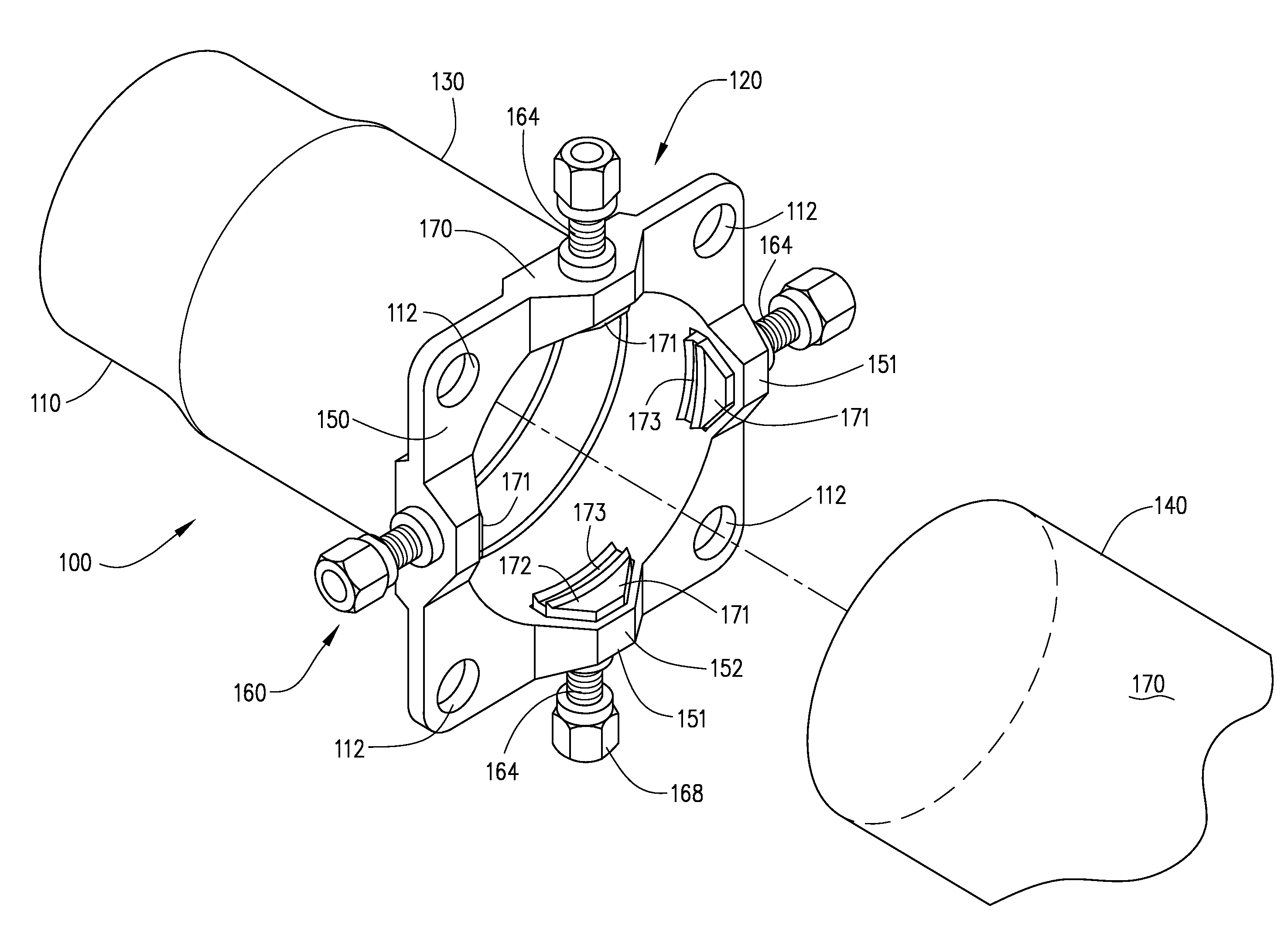
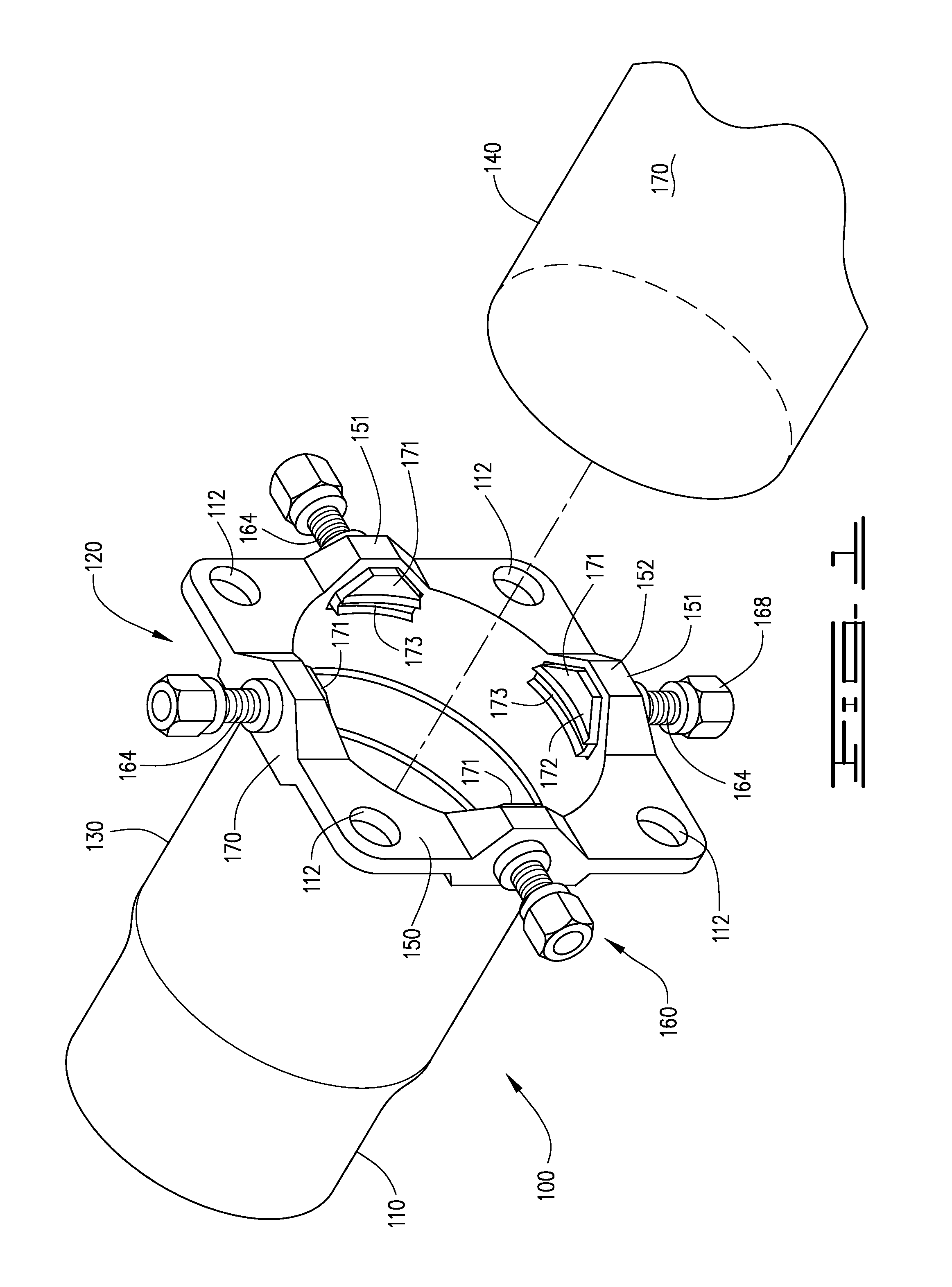
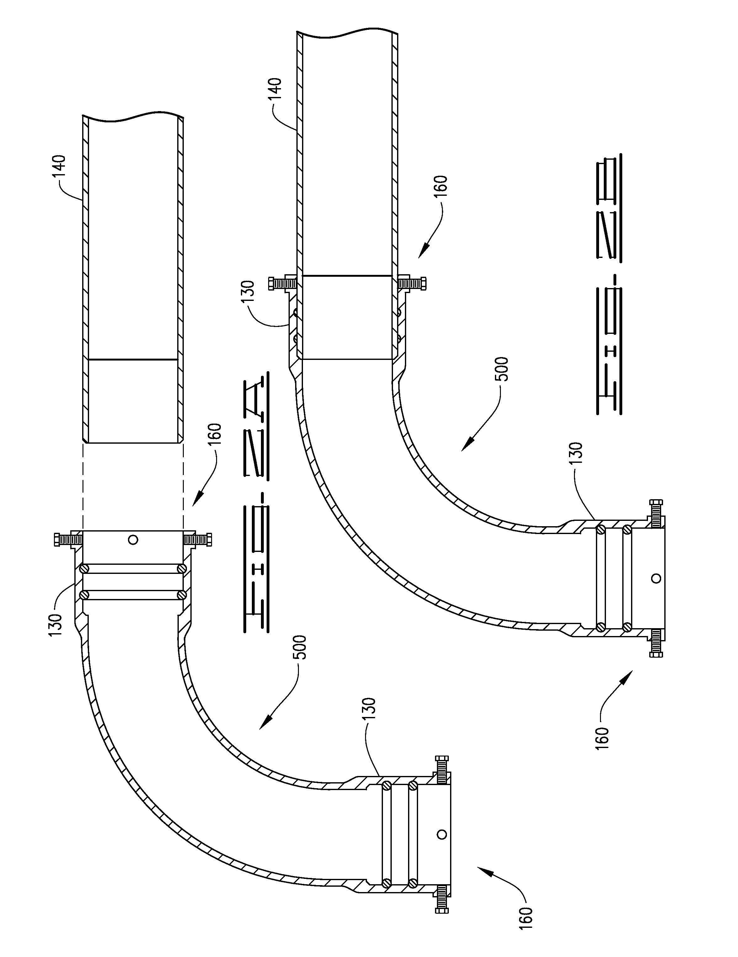
[0034]Broadly, the current invention includes systems, devices, and methods providing a bell-and-spigot type of joint architecture for joining two lengths of pipe or joining a length of pipe to a fitting by use of a fastening mechanism that is integral to the pipe end or to the fitting. Fittings contemplated for use with the invention may include valves, elbows, terminating devices, and other such devices having a bell-shaped receptacle that receives a pipe end. The invention comprises an improved restrained push-on connection for push-on pipe, which is a hybrid of the push-on and mechanical connection architectures. Portions of the restraint mechanism ...


PUM

PropertyMeasurementUnit
pressuresaaaaaaaaaa
groove depthaaaaaaaaaa

Abstract

An apparatus, system, and method for the secure attachment and restraint of a pipe end within a fitting is disclosed. The invention includes a mechanical restraint apparatus that is integral and monolithic with the flange of a bell of a spigot-and-bell joint architecture, along with one or more internally disposed grooves within the bell that receive a circumferential gasket, in order to maintain a seal about the pipe end when it is inserted into the bell. The inventive apparatus combines features of mechanical connections and push-on connections.

Description

CROSS-REFERENCES TO RELATED APPLICATIONS[0001]This application claims the benefit of U.S. Provisional Patent Application No. 61 / 068,570, filed on Mar. 7, 2008, entitled “Specifications for a Restrained Push-On Connection for Push-On Pipe,” the contents of which are hereby incorporated by reference in their entirety.BACKGROUND OF THE INVENTION[0002]The present invention generally relates to methods and devices for coupling pipes together and more particularly relates to a integral restraining mechanism for an end of a pipe that sealingly holds another pipe, conduit, valve housing, or similar member in coupled relationship with the pipe.[0003]Over the years, various devices and methods have been used to couple pipe of all types with other pipe, valves, various pipe fittings, hydrants, and miscellaneous connections, where pipe is secured to another member and thereafter subjected to internal fluid pressure which tends to separate the pipe from the member to which it is coupled. Typical...

Claims


Application Information

Patent Timeline
Patent Type & Authority Patents(United States)
IPC IPC(8): F16L21/00
CPCF16L21/08F16L25/065Y10T29/49963
Inventor SMITH, JR., FRED R.JONES, WILLIAM L.
Owner SMITH JONES ENTERPRISES
Why Eureka
Try Eureka