1D or 2D goniometry method of diffuse sources

Inactive Publication Date: 2011-08-16
THALES SA
View PDF2 Cites 9 Cited by
  • Summary
  • Abstract
  • Description
  • Claims
  • Application Information

AI Technical Summary

Benefits of technology

[0024]The method can include a step of limited development of the vectors of the matrix D(θ, δθ), the minimizing step being performed on a matrix U(θ) in order to determine

Problems solved by technology

Conversely, these signals are incoherent when they are strongly

Method used


Image

  • 1D or 2D goniometry method of diffuse sources
  • 1D or 2D goniometry method of diffuse sources
  • 1D or 2D goniometry method of diffuse sources

Examples


Example

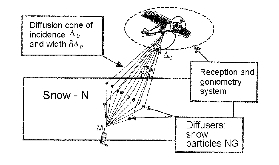
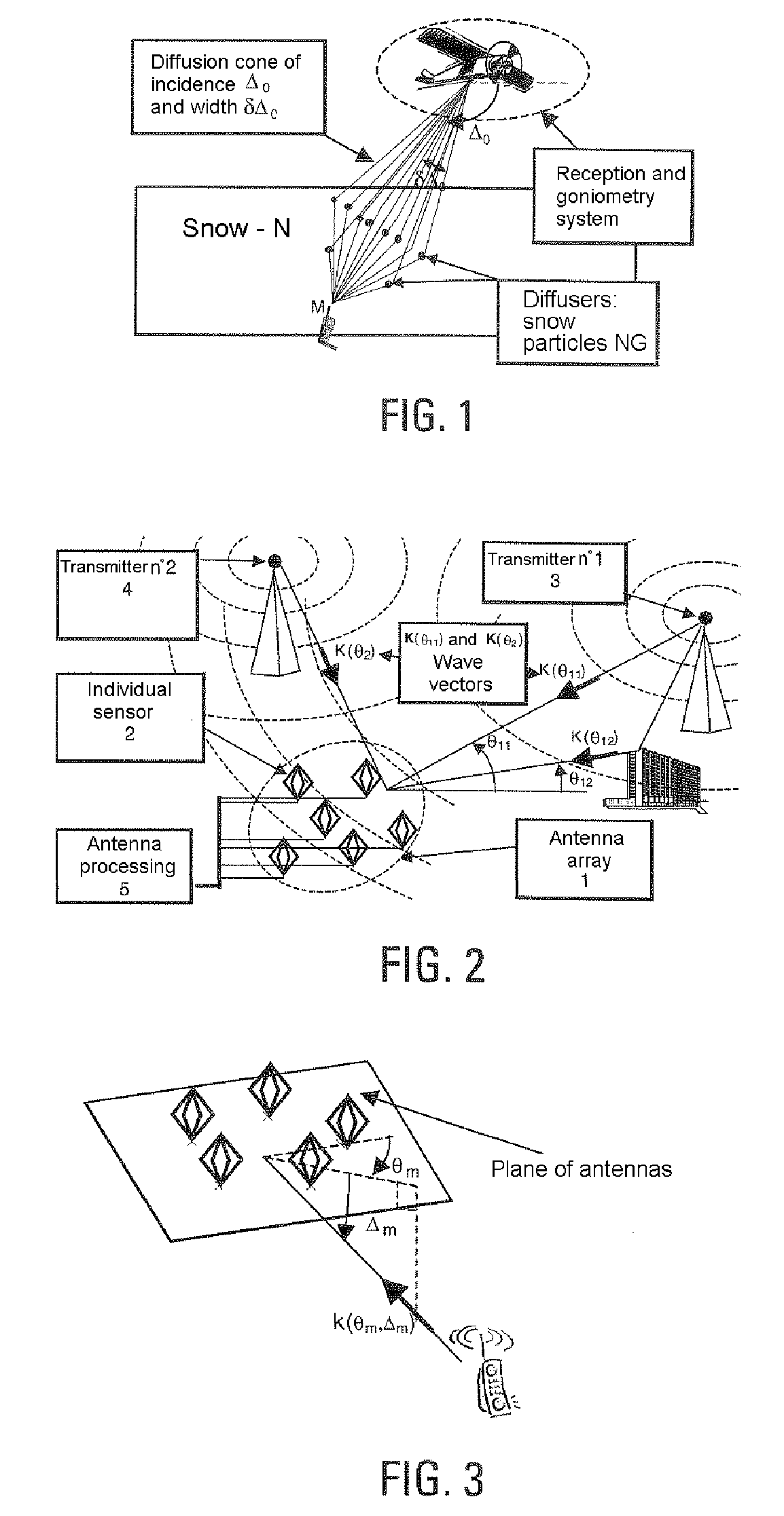
[0045]In order to better understand the method according to the invention, the description that follows is given, as an illustration and in a nonlimiting way, in the context of the diffusion of the wave from a cell phone through a layer of snow to the receivers on an airplane, for example represented in FIG. 1. The snow particles act as diffusers.

[0046]In this example, a diffuse or distributed source is characterized, for example, by a direction and a diffusion cone.

[0047]Before detailing the exemplary embodiment, a few reminders are given that may be helpful in understanding the method according to the invention.

General Case

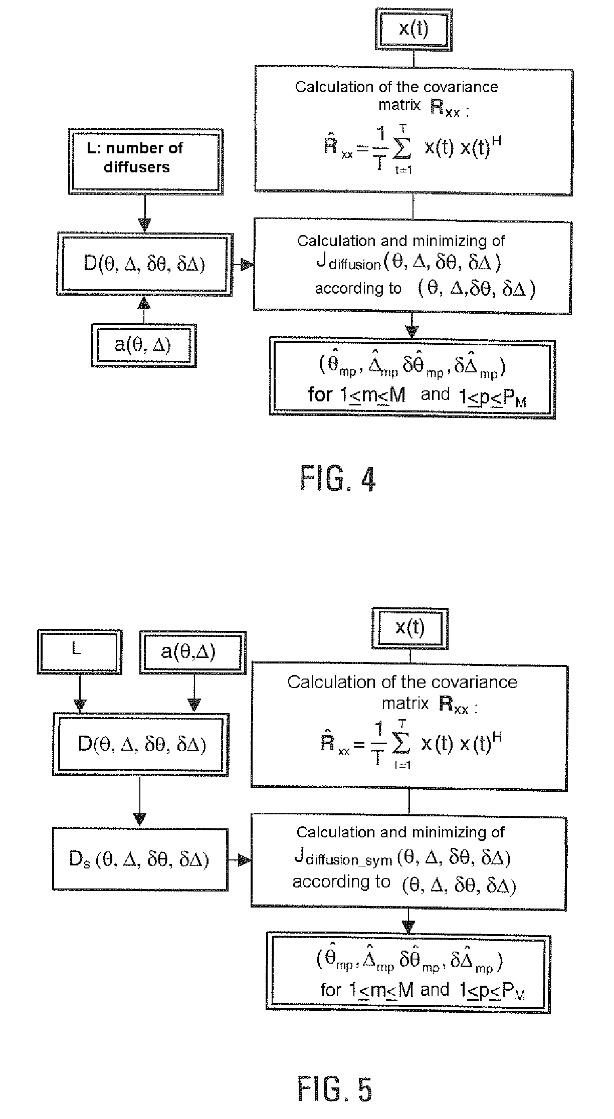
[0048]In the presence of M transmitters being propagated along Pm non-distributed multiple paths of incidences (θmp, Δmp) arriving at an array consisting of N sensors, the observation vector x(t) below is received at the output of the sensors:

[0049]x⁡(t)=⁢[x1⁡(t)⋮xN⁡(t)]=⁢∑m=1M⁢⁢∑p=1Pm⁢ρm⁢⁢p⁢a⁡(θm⁢⁢p,Δm⁢⁢p)⁢sm⁡(t-τm⁢⁢p)⁢ⅇj⁢⁢2⁢π⁢⁢fmp⁢⁢t+b⁡(t)(1)

where xn(t) is the...


PUM


Abstract

A goniometry method for one or several diffuse (or distributed) sources is disclosed. The sources or sources having one or more give directions and a diffusion cone. The sources are received by an array of several sensors. The method breaks down the diffusion cone into a finite number L of diffusers. A diffuser has the parameters (θmp, δθmpi, Δmp, δΔmpi), associated with it. Directing vectors a(θmp+δθmpi, Δmp+δΔmpi) associated with the L diffusers are combined to obtain a vector (D(θ, Δ, δθ, δΔ) α or U(θ, Δ) β(δθ, δΔ, α)) dependent on at least one of the incidence and deflection parameters (θ, Δ, δθ, δΔ) and on the combination vector α. A MUSIC-type criterion or other goniometry algorithm is applied to the vectors D(θ, Δ, δθ, δΔ) α or U(θ, Δ) β(δθ, δΔ, α) obtained in order to determine at least one of the incidence parameters θmp, Δmp, δθmp, δΔmp of the associated diffusion cone.

Description

RELATED APPLICATIONS[0001]The present Application is based on International Application No. PCT / EP2005 / 050430, filed on Feb. 1, 2005, which in turn corresponds to French Application No. 02 11072 filed on Sep. 6, 2002, and priority is hereby claimed under 35 USC §119 based on these applications. Each of these applications are hereby incorporated by reference in their entirety into the present application.FIELD OF THE INVENTION[0002]The present invention relates to a goniometry method for one or more diffuse, or “distributed”, radiofrequency sources, the source of given direction being considered by the receivers as a diffusion cone with a certain width and an average incidence.BACKGROUND OF THE INVENTION[0003]A distributed source is defined notably as a source which is propagated through a continuum of diffusers.[0004]The invention makes it possible notably to locate, in angles and / or in azimuth, one or more distributed radio frequency sources. The object is, for example, to determin...

Claims


Application Information

Patent Timeline
IPC IPC(8): G01S3/12
CPCG01S3/74
Inventor FERREOL, ANNEVIBERT, BLANDINEMORGAND, PHILIPPE
Owner THALES SA
Why Eureka
Try Eureka