Image forming apparatus with a cleaning device
a technology of cleaning device and image forming apparatus, which is applied in the direction of electrographic process apparatus, instruments, optics, etc., can solve the problems of time-consuming and complicated maintenance work, and achieve the effect of reducing the overall size reducing the height of the image forming apparatus, and facilitating maintenance work for the cleaning uni
- Summary
- Abstract
- Description
- Claims
- Application Information
AI Technical Summary
Benefits of technology
Problems solved by technology
Method used
Image
Examples
first embodiment
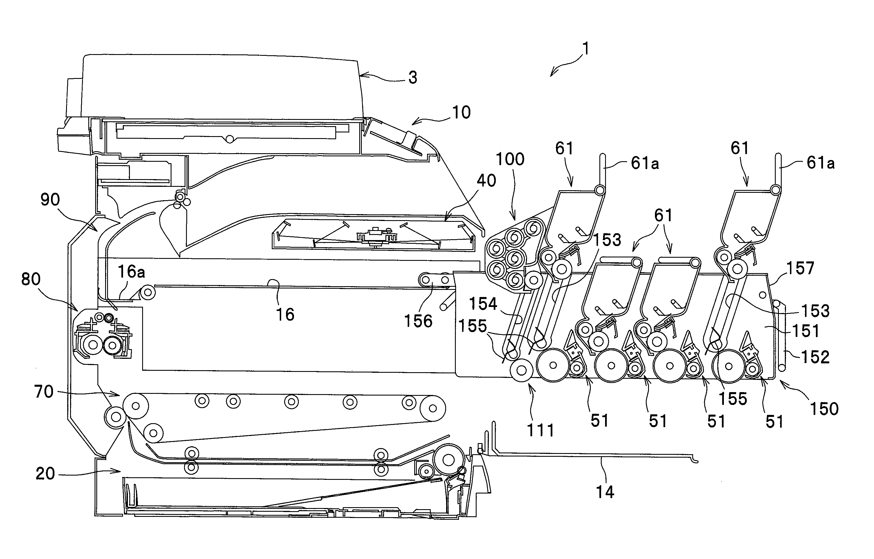
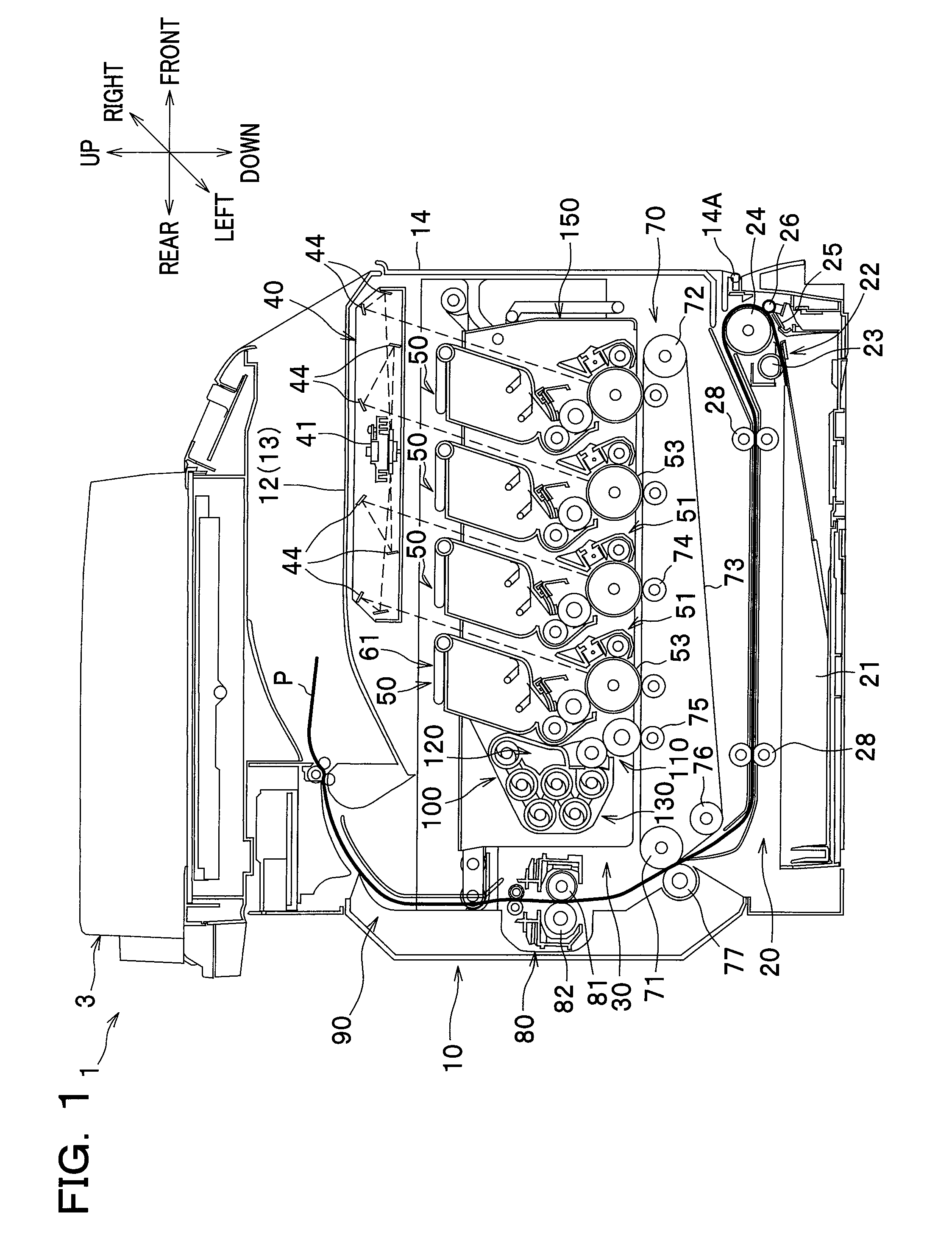
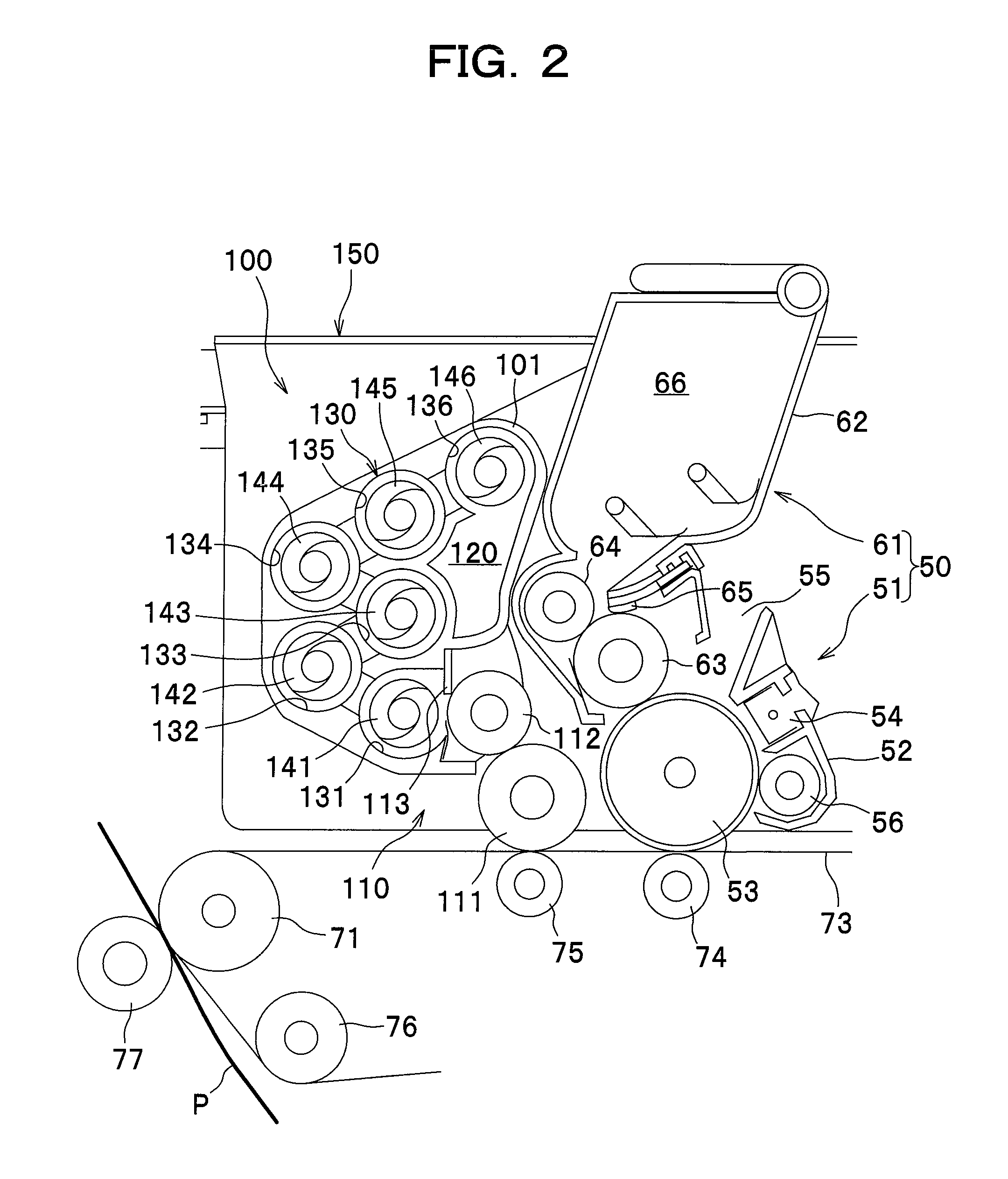
[0029]As seen in FIG. 1, a color printer 1 has a main body 10. The color printer 1 is provided with a sheet feeding unit 20 configured to feed a sheet of paper P (hereinafter simply referred to as a “sheet” P) as an example of a recording sheet, an image forming device 30 configured to form an image on the sheet P supplied from the sheet feeding unit 20, and a sheet output unit 90 configured to discharge the sheet P having the image thereon from the main body 10, which are arranged in the main body 10. The color printer 1 is also provided with a flat-bed scanner 3 at an upper part of the main body 10.
[0030]An upper cover 12 is provided at an upper part of the main body 10. Also, a front cover 14 is provided at a front part of the main body 10. The front cover 14 is pivotally supported on a hinge 14A that is provided at a lower part of the main body 10. The front cover 14 is swung open and closed in the front-and-rear direction around the hinge 14A. The upper surface of the upper cov...
second embodiment
[0092]A second embodiment of the present invention will be described below. In the following description, parts different from those employed in the first embodiment will be mainly described, and like or similar parts will be denoted by the same reference numerals and the same names as those in the first embodiment and description thereof will be omitted or briefly stated.
[0093]In the following description, unless otherwise stated, directions of a color printer refer to the directions as seen from a user facing the color printer during its use. To be more specific, referring to FIG. 6, a left-side direction and a right-side direction of the color printer are referred to as a “front side” and a “rear side”, respectively. Also, a direction away from a viewer of FIG. 6 is referred to as a “left side”, and a direction toward the viewer of FIG. 1 as a “right side”. An upper and lower direction in FIG. 6 is referred to as a “vertical direction” or an “upper and lower direction” as it is.
[...
third embodiment
[0113]With reference to FIG. 8, a color printer 1B according to a third embodiment of the present invention will be described.
[0114]The color printer 1B according to the third embodiment is substantially the same in construction as the color printer 1A according to the second embodiment except for the cleaning unit 300.
[0115]To be more specific, the cleaning unit 300 includes a cleaning blade 301 which contacts with the intermediate transfer belt 73. The cleaning blade 301 is a thin plate-like elongated member, for example, made of urethane rubber. The cleaning blade 301 extends in the right-and-left directions at the upper end portion of the cleaning unit 300. It is noted that the cleaning unit 300 does not comprise a cleaning roller and a collecting roller unlike the cleaning unit 100 (see FIG. 2) provided with the cleaning roller 111 and the collecting roller 112.
[0116]Because the cleaning blade 301 contacts with the intermediate transfer belt 73, toner T adhering to the intermed...
PUM
 Abstract
Description
Claims
Application Information
 - R&D
- Intellectual Property
- Life Sciences
- Materials
- Tech Scout
- Unparalleled Data Quality
- Higher Quality Content
- 60% Fewer Hallucinations
Browse by: Latest US Patents, China's latest patents, Technical Efficacy Thesaurus, Application Domain, Technology Topic, Popular Technical Reports.
© 2025 PatSnap. All rights reserved.Legal|Privacy policy|Modern Slavery Act Transparency Statement|Sitemap|About US| Contact US: help@patsnap.com


