Receptacle

a technology for receptacles and plug-in modules, which is applied in the direction of coupling devices, coupling device connections, coupling device parts engagement/disengagement, etc., and can solve problems such as the difficulty of unplugging the plug-in module from the receptacl

Inactive Publication Date: 2011-08-23
CHENG UEI PRECISION IND CO LTD
View PDF7 Cites 0 Cited by
  • Summary
  • Abstract
  • Description
  • Claims
  • Application Information

AI Technical Summary

Benefits of technology

It is an object of the present invention to provide a receptacle capable of receiving a plug-in module firmly as well as releasing the plug-in module conveniently.
As the above description, the locking portion of the first resilient strip could buckle to the depression of the plug-in module and the control element could drive the locking portion to depart from the depression of the plug-in module for allowing the plug-in module to move outward under the pulling of the elastic element. Therefore, the receptacle is able to receive the plug-in module firmly and release the plug-in module conveniently.

Problems solved by technology

Moreover, it is difficult to unplug the plug-in module from the receptacle, when the plug-in module is required to use, because of lack of a driving structure for driving the plug-in module exit from the receptacle.

Method used


Image

  • Receptacle
  • Receptacle
  • Receptacle

Examples


Embodiment Construction

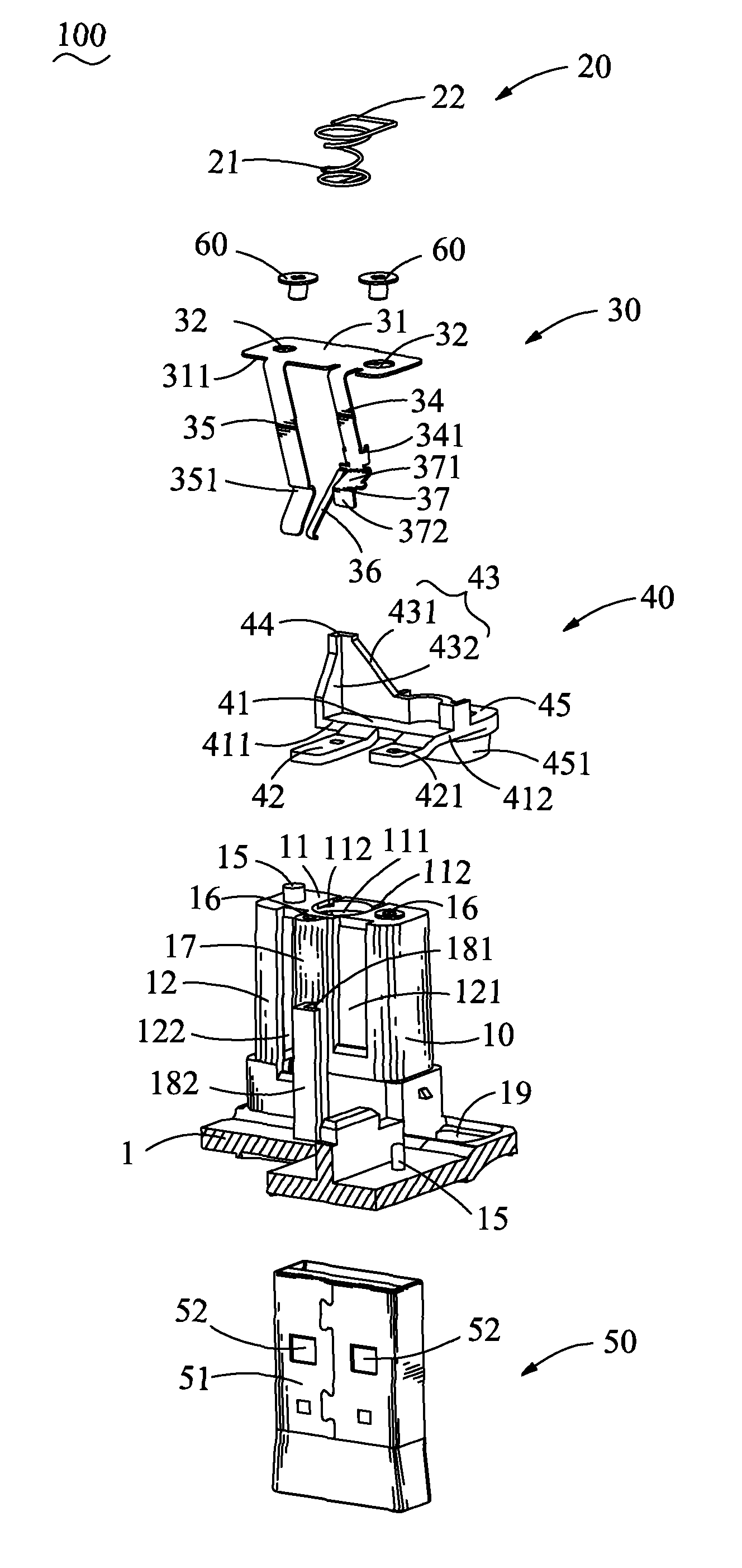
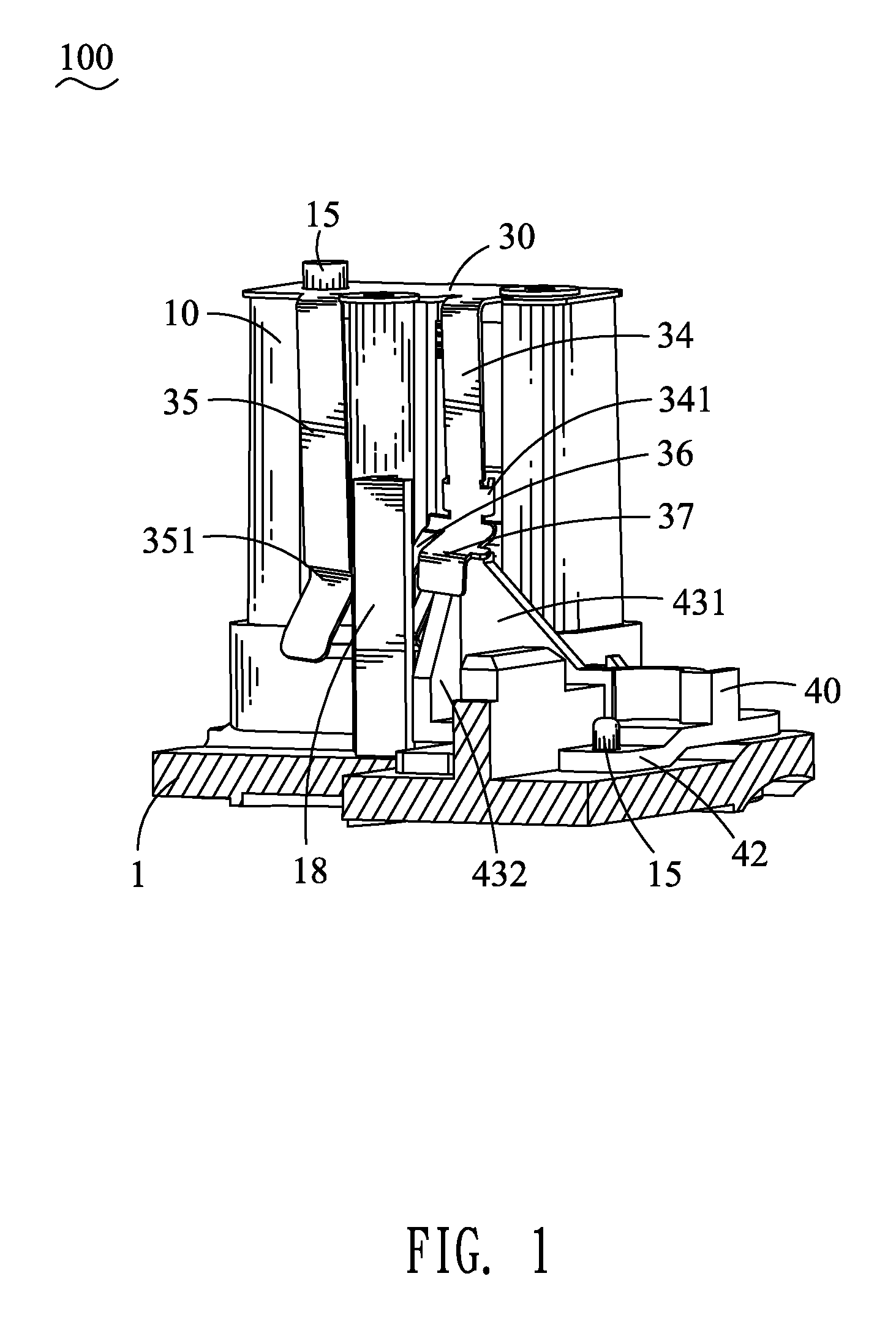
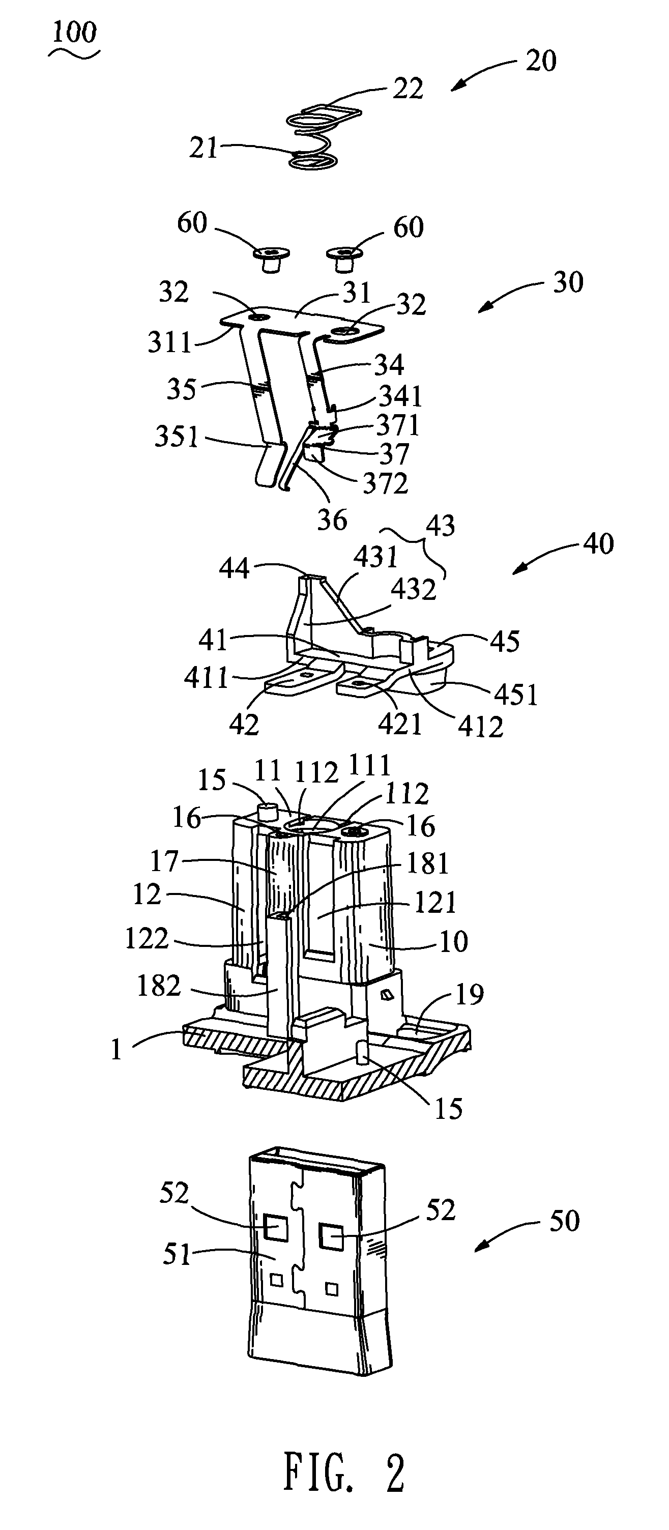
Referring to FIGS. 1 and 2, the receptacle 100 in accordance with the present invention includes a base plate 1, a main body 10, an elastic element 20, an elastic piece 30 and a control element 40.

With referring to FIGS. 1, 2 and 4, the main body 10 protrudes upward from the base plate 1 which is a part of a case of a portable electronic device. The main body 10 shows substantially a rectangular shape and includes a top surface 11, a front surface 12 and a rear surface (not shown). The main body 10 further includes a receiving chamber 13 penetrating the top surface 11 and the base plate 1, and then respectively forms a circular hole 111 in a middle of the top surface 11 and a rectangular insertion opening 14 on the base plate 1. A plural of ridges 131 extend inward on inner surfaces 132 of the receiving chamber 13. A pair of grooves 112 penetrates a rear edge of the top surface 11 and extends frontward to connect the circular hole 111. Each of the grooves 112 is perpendicular to the...


PUM


Abstract

A receptacle for receiving a plug-in module with at least one depression at a side surface thereof includes a main body, an elastic element, a first resilient strip and a control element. The main body has a receiving chamber penetrating a bottom thereof for engaging the plug-in module and a first slot extending up and down defined in a front surface thereof and connecting the receiving chamber. The elastic element has an elastic portion received in an upper portion of the receiving chamber. The first resilient strip is received in the first slot, and defines a locking portion extending rearward at a lower portion thereof and penetrating into the receiving chamber for buckling to the depression of the plug-in module. The control element is for driving the locking portion to depart from the depression of the plug-in module for allowing the plug-in module to move outward due to the pulling of the elastic element.

Description

BACKGROUND OF THE INVENTION1. Field of the InventionThe present invention relates to a receptacle, and in particular to a receptacle capable of receiving a plug-in module firmly as well as releasing the plug-in module conveniently.2. The Related ArtNowadays, in order to expand the function thereof and use conveniently, a portable electronic device has a unplugable plug-in module of particular function. The portable electronic device includes a receptacle disposed therein. The receptacle has an insertion opening exposed outside for receiving the plug-in module.A special plug-in module, such as a USB module, includes a metal shell with an opening defined at a side plate thereof. Conventionally, the receptacle has an elastic locking structure for elastically resisting against the metal shell of the plug-in module, when the plug-in module is inserted therein. But, when the portable electronic device suffers from an outer force, the plug-in module is easy to produce a displacement corres...

Claims


Application Information

Patent Timeline
Patent Type & Authority Patents(United States)
IPC IPC(8): H01R13/62
CPCH01R4/26H01R13/187
Inventor LEE, TSUNG-SHIH
Owner CHENG UEI PRECISION IND CO LTD
Why Eureka
Try Eureka