Light switch assembly

a technology for light switches and assembly parts, which is applied in the direction of lighting and heating apparatus, casings/cabinets/drawers, electrical apparatus casings/cabinets/drawers, etc., can solve the problems of unattractive covers, inoperability of covered light switches, and difficulty in attaching rigid light switch covers

Inactive Publication Date: 2011-08-23
RINTZ WILLIAM J
View PDF14 Cites 98 Cited by
  • Summary
  • Abstract
  • Description
  • Claims
  • Application Information

AI Technical Summary

Benefits of technology

[0017]It is another object of the present invention to provide a light switch cover that fully shields the rocker switch and receptacle from external access for safety purposes.
[0018]It is a further object of the present invention to provide a light, switch cover made of flexible materials to allow the covered rocker switch to be operable.
[0019]It is still another object of the present invention to provide a tight switch cover which provides aesthetic features.
[0020]It is yet another object of the present invention to provide a light switch cover which will illuminate when the rocker switch is in an “off” position.

Problems solved by technology

Three disadvantages associated with the use of rigid light switch covers are (1) inoperability of covered light switch; (2) unattractiveness of the cover, and (3) difficulties in attaching the rigid light switch cover.

Method used


Image

  • Light switch assembly
  • Light switch assembly
  • Light switch assembly

Examples


first embodiment

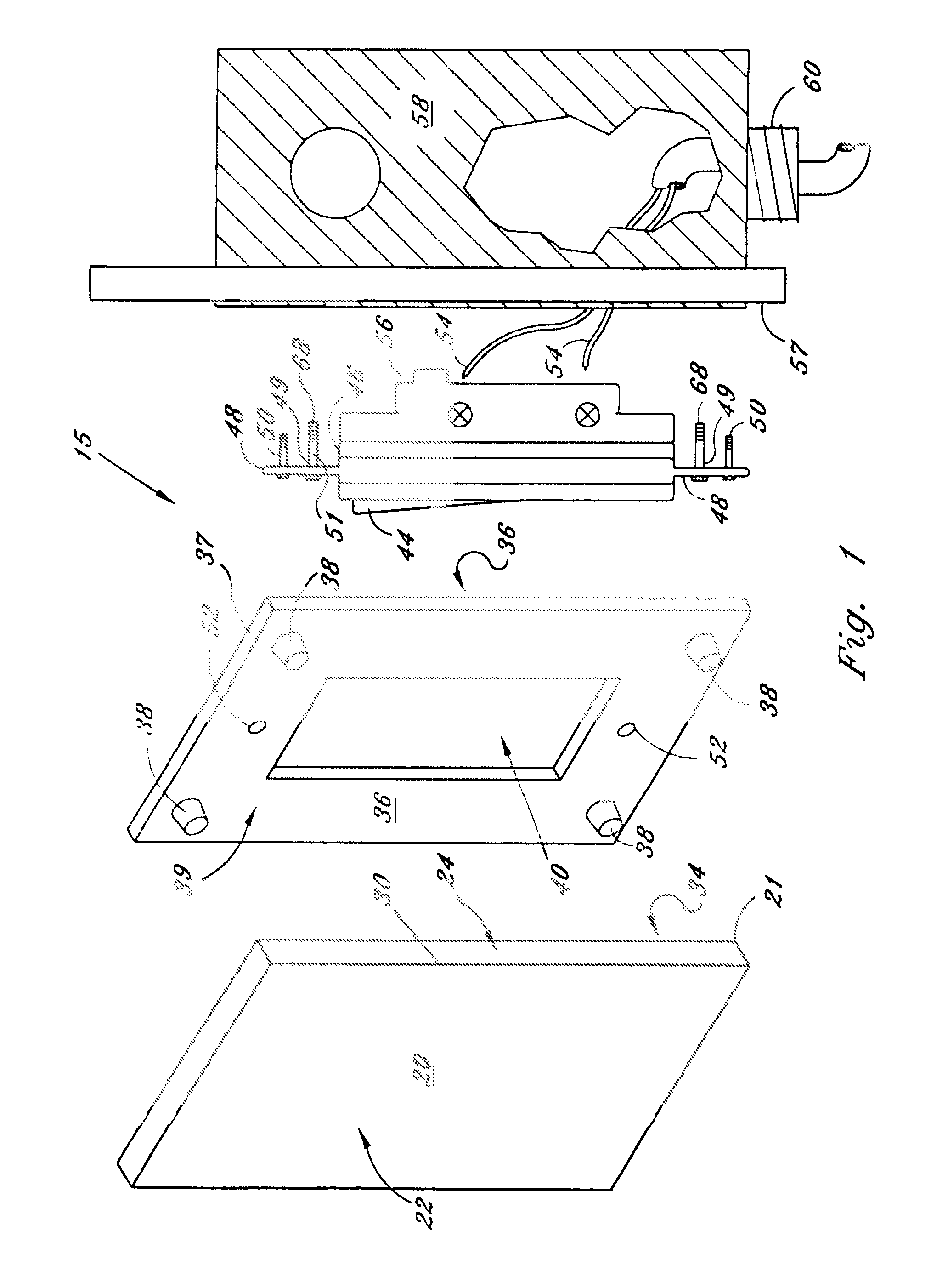
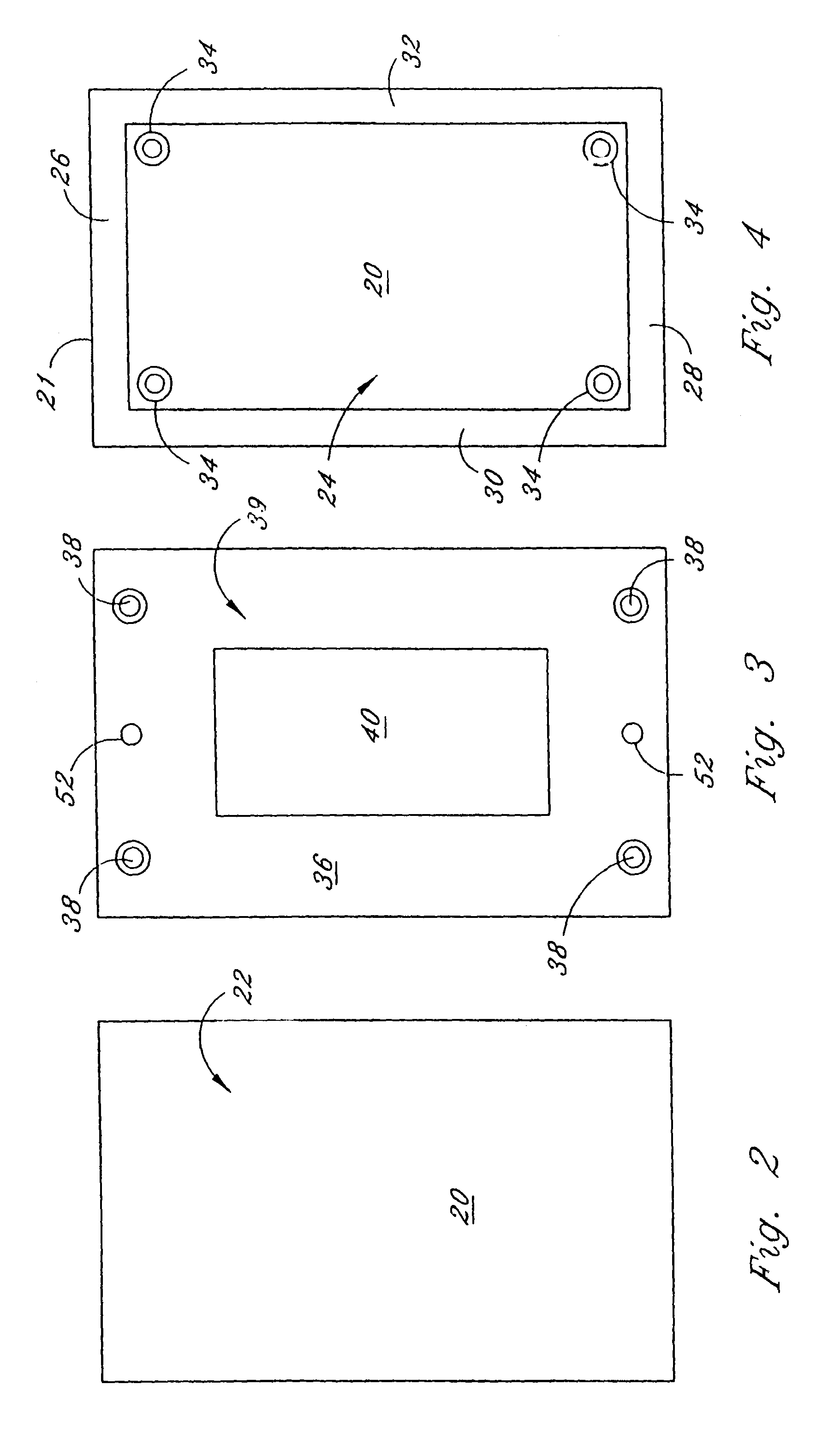
[0079]As seen in FIGS. 1 through 4, the present invention light switch cover is shown and generally designated as reference numeral 15. Cover 15 generally consists of a face plate 20 and a mourning bracket 36. Face plate 20 consists of a body member 21 having an outer surface 22 and inner surface 24. A top lip 26, a bottom lip 28, a first side lip 30, and a second side lip 32 can be provided and are preferably, constructed integral to respective edge portions of body member 21. Face plate 20 is preferably constructed from a castable, soft, flexible material such as neoprene, silicone, vinyl, etc., to allow a conventional rocker switch 46 to be operated while face plate 20 is disposed over rocker switch 46 for safety purposes. Though not preferred, face plate 20 can also be constructed from a rigid plastic or the like. However, with the rigid material, the user cannot utilize covered rocker switch 46. Outer surface 22 can be provided with any type of decorative design or indicia. Out...

third embodiment

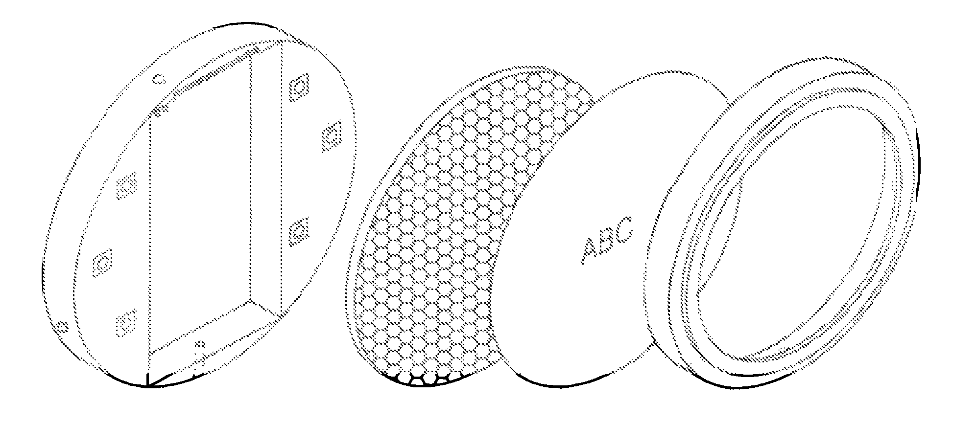
[0090]FIGS. 8 through 10 illustrate the present invention wherein the light switch cover is generally designated as reference numeral 200. In this embodiment, light, switch cover 200 is generally provided with a face plate 210, mounting bracket 220, and electroluminescent lighting sheet or panel 240. Electroluminescent lighting sheet 240 highlights or enhances a design disposed on an outer surface of face plate 210, or itself can be a lighting effect design in lieu of a design on the outer surface of face plate 210. Additionally, a screen print design can be directly applied to lighting sheet 240, as well as face plate 210. Where a screen print design is applied to lighting sheet 240, face plate 210 can merely be a clear cover. Lighting sheet 240 can provide cool, bright, uniform panels of light, which can create a combination of various colors of light or a single color depending on the user's preference. Lighting sheet 240 can also be constructed to provide light patterns in an en...

second embodiment

[0094]Similar to the present invention, a light switch cover assembly, including an electroluminescent lighting sheet can also be utilized where more than one rocker switch is provided. Where more than one rocker switch is provided, the lighting sheet is larger in width as compared to lighting sheet 240 and the length of its width is dependent on the number of rocker switches provided. Additionally, a diverter bar, as described above, is provided. Also, the safety attachment of a mounting bracket outer flange and flange groove member, as described above, can also be provided for all of the embodiments of the present invention. Furthermore, where an attachment sheet is utilized, the attachment sheet is larger in width than attachment sheet 260 and the length of its width is dependent on the number of rocker switches provided.

[0095]Wires 242 can be connected to switch box 56, by conventional means, so that when rocker switch 46 is in an “off” position, lighting sheet 240 is illuminate...


PUM


Abstract

A light switch assembly to replace an existing light switch, which generally includes a mounting bracket attached to an electrical box. The assembly slides into the mounting bracket and is locked into place with the mounting bracket. A decorative light switch cover and custom artwork within the frame snaps and locks onto the outer perimeter of the mounting bracket to complete the assembly. The assembly provides for a battery hack-up system for power failure situations to illuminate the white, light emitting diodes in the event of a loss of power. The assembly senses the loss of power and unlocks the switch assembly from attachment to the mounting bracket. Unsnapping the decorative cover exposes the switch assembly so it can be removed from the mounting bracket. The switch assembly then becomes a mobile, hand-held emergency flashlight. The battery back-up system also allows for communication with first responders.

Description

CROSS-REFERENCE TO RELATED APPLICATIONS[0001]This application is a continuation-in-part of U.S. application Ser. No. 11 / 858,580, filed Sep. 20, 2007, which is a continuation-in-part of U.S. application Ser. No. 11 / 369,207, filed Mar. 6, 2006, now U.S. Pat. No. 7,273,983, which is a continuation-in-part of U.S. application Ser. No. 10 / 912,746, filed Aug. 5, 2004, now U.S. Pat. No. 7,009,111, which is a continuation-in-part of U.S. application Ser. No. 10 / 643,230, filed Aug. 18, 2003 (Abandoned), which is a continuation-in-part of application Ser. No. 10 / 094,746, filed Mar. 11, 2002, now U.S. Pat. No. 6,608,253, which is a continuation-in-part of application Ser. No. 09 / 550,532, filed Apr. 17, 2000, now U.S. Pat. No. 6,355,855, which is a continuation-in-part of application Ser. No. 09 / 009,710, filed on Jan. 20, 1998, now U.S. Pat. No. 6,051,787, which is a continuation-in-part of application Ser. No. 08 / 826,643, filed on Apr. 4, 1997, now U.S. Pat. No. 5,874,693, which is a continuat...

Claims


Application Information

Patent Timeline
Patent Type & Authority Patents(United States)
IPC IPC(8): H05H5/03
CPCH01H9/0235H01H9/182H02G3/14F21V23/04H05B33/0845H01H9/167F21Y2101/02H01H23/14F21Y2115/10H05B45/10
Inventor RINTZ, WILLIAM J.
Owner RINTZ WILLIAM J
Why Eureka
Try Eureka