Image forming apparatus and image forming method

a technology of image forming apparatus and forming method, which is applied in the direction of electrographic process apparatus, instruments, optics, etc., can solve the problems of increasing the inability to accurately detect the densities so as to reduce the amount of waste toner and toner consumption without deteriorating the detecting accuracy of the detection pattern, the effect of reducing the tim

Inactive Publication Date: 2011-08-23
KONICA MINOLTA BUSINESS TECH INC
View PDF19 Cites 2 Cited by
  • Summary
  • Abstract
  • Description
  • Claims
  • Application Information

AI Technical Summary

Benefits of technology

[0008]An object of the invention is to provide an image forming apparatus which decreases the waste toner amount and toner consumption and reduces the time taken to detect densities of detection patterns while maintaining the detecting accuracy thereof.
[0010]According to the first aspect of the present invention, the control section stores the detection result of the toner amount detecting section regarding the detection pattern. When a detection pattern is formed on the conveying rotation unit, the control section determines a circumference-directional length of the detection pattern formed this time, based on the detection result of the toner amount detecting section regarding a detection pattern formed immediately before. Therefore, when the detection pattern formed immediately before has a large amount of adhering toner, the detection pattern this time is formed to have a pattern length shortened. This makes it possible to decrease the waste toner amount and toner consumption without deteriorating the detecting accuracy of the detection pattern. It also becomes possible to reduce the time taken to detect the toner adhering amount of the detection pattern. Herein, it should be noted that “a circumference-directional length of the detection pattern” is defined as a length of the detection pattern in the circumferential direction of the intermediate transfer belt, that is, in the rotational transfer direction of the intermediate transfer belt.
[0012]According to the second aspect of the present invention, when a detection pattern is formed on the conveying rotation unit, the control section determines a circumference-directional length of the detection pattern formed this time, based on the detection result of the toner amount detecting section regarding a detection pattern formed immediately before. Therefore, as in the case of the first aspect of the invention, when the detection pattern immediately before has a large amount of adhering toner, the detection pattern this time is formed to have a pattern length shortened. This makes it possible to decrease the waste toner amount and toner consumption without deteriorating the detecting accuracy of the detection pattern. It also becomes possible to reduce the time taken to detect the toner adhering amount of the detection pattern.
[0014]According to the third aspect of the present invention, a circumference-directional length of the detection pattern formed this time on the outer surface of the conveying rotation unit is set based on the toner adhering amount formed and stored immediately before. Therefore, as in the case of the first and second aspects of the invention, when the detection pattern formed immediately before has a large amount of adhering toner, the detection pattern this time is formed to have a pattern length shortened. This makes it possible to decrease the waste toner amount and toner consumption without deteriorating the detecting accuracy of the detection pattern. It also becomes possible to reduce the time taken to detect the toner adhering amount of the detection pattern.

Problems solved by technology

When densities of detection patterns are low, irregularity in densities becomes pronounced.
Under harmful influence of the density irregularity, outputs from the density sensor may be greatly varied, so that it becomes impossible to accurately detect the densities of the detection patterns.
In the conventional image forming apparatus, however, there have been a problem that the amounts of waste toner and toner consumption are increased, and a problem that time taken to detect the densities of detection patterns becomes long because each length of the detection patterns is longer than the peripheral length of the photoconductor.

Method used


Image

  • Image forming apparatus and image forming method
  • Image forming apparatus and image forming method
  • Image forming apparatus and image forming method

Examples


Embodiment Construction

[0028]Hereinbelow, embodiments of the present invention will be described in details with reference to the drawings by way of illustration.

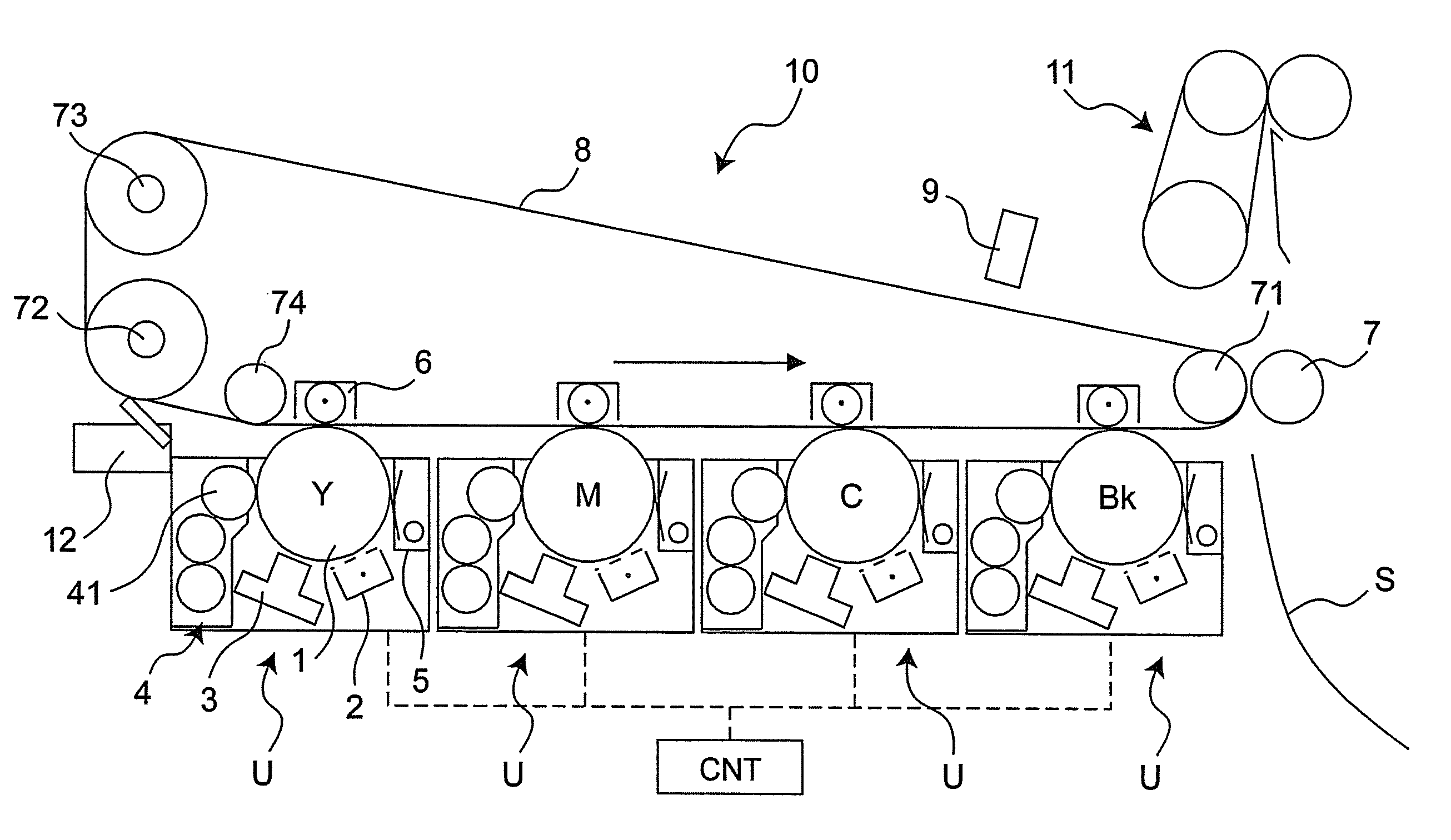
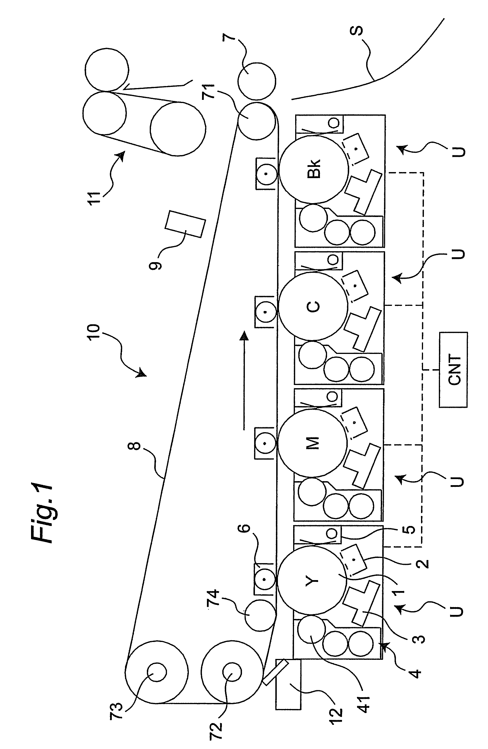
[0029]An image forming apparatus in one embodiment of the present invention is shown in FIG. 1. The imaging device 10 is composed of an imaging device 10 and a fixing device 11. The imaging device 10 is for attaching unfixed toner to recording paper sheets S so as to form images. The fixing device 11 is for melting the toner and fixing it to the recording paper sheets. The image forming apparatus is an electrophotographic four-color color printer.

[0030]The imaging device 10 has an intermediate transfer belt 8, four image forming units U, a primarily transfer roller 6, and a secondary transfer roller 7. The four image forming units U are placed along the intermediate transfer belt 8 for forming toner images. The primarily transfer roller 6 transfers the toner images formed by each of the image forming units U onto the intermediate transfer belt 8....


PUM


Abstract

An image forming apparatus is provided with a control section which stores detection results of a toner sensor regarding detection patterns. When forming a plurality of detection patterns on an intermediate transfer belt, the control section determines circumference-directional lengths of the detection patterns formed this time, based on the detection results of the toner sensor regarding the detection patterns formed immediately before. Thereby, the waste toner amount and toner consumption are not only decreased but also the time taken to detect the density of a detection pattern is reduced, while maintaining the detecting accuracy thereof.

Description

CROSS-REFERENCE TO RELATED APPLICATION[0001]This application is based on application No. 2008-156314 filed in Japan, the entire content of which is hereby incorporated by reference.BACKGROUND OF THE INVENTION[0002]The present invention relates to an image forming apparatus such as a copying machines, a laser printer and a facsimile, and relates to a image forming method.[0003]Generally, image density of toner images in an image forming apparatus may be changed due to disturbances such as an environmental change in temperature or humidity around the apparatus or a change in durability of the apparatus.[0004]In order to stabilize the image density, one of conventional image forming apparatuses forms test toner images (hereinafter referred to as “detection patterns”) on a photoconductor, so that a developing bias, which affects the image density, is optimized on the basis of densities of the detection patterns (see JP 2004-61809 A).[0005]Specifically, the developing bias is variously c...

Claims


Application Information

Patent Timeline
Patent Type & Authority Patents(United States)
IPC IPC(8): G03G15/00
CPCG03G15/0131G03G15/5058G03G2215/00059
Inventor HARASHIMA, TAKASHIYAMADA, OSAMU
Owner KONICA MINOLTA BUSINESS TECH INC
Why Eureka
Try Eureka