Device for cutting slits in a surface

a technology of cutting slits and surface, which is applied in the direction of lawn mowers, agriculture tools and machines, etc., can solve the problems of unpredictability of golf balls, particularly undesirable turf cover, adversely affecting the performance characteristics of turf covers in the case of playing fields, etc., and achieves the effect of reducing these drawbacks

Inactive Publication Date: 2011-08-30
GEBRR KRAAIJEVELD
View PDF14 Cites 0 Cited by
  • Summary
  • Abstract
  • Description
  • Claims
  • Application Information

AI Technical Summary

Benefits of technology

[0004]In a preferred embodiment of the device according to the invention the cutter can be moved in order to throw up material from the surface in a throw-up direction. In an additional embodiment of the device according to the invention the collecting means are located in the throw-up direction. These measures have the advantage that, in addition to the cutter, no additional means are necessary for the purpose of carrying the cut-away material from the surface to the collecting means.
[0019]In a further additional embodiment of the device according to the invention the device comprises a slit blade a short distance behind the cutter relative to the direction of displacement of the device, which blade extends at least during use in a cut slit. This slit blade makes it possible to correct unevenness in the slit as a result of the cutting. Particularly in a device according to the invention where the slit is filled with filler material, the slit blade has the advantage that the slit does not collapse before it is filled with filler material.

Problems solved by technology

In addition to the fact that this material which has been cut away and left behind can inhibit the growth of the grass, this material adversely affects the performance characteristics of the turf cover in the case of for instance playing fields.
On golf courses material on the turf cover is particularly undesirable, for instance on the green, where the golf ball rolls over the turf cover.
This is because, as a result of the material on the turf cover, the golf ball will behave unpredictably, to the detriment of enjoyment in playing.
The material left behind moreover has an adverse effect on the appearance of the turf cover.

Method used


Image

  • Device for cutting slits in a surface
  • Device for cutting slits in a surface
  • Device for cutting slits in a surface

Examples


Embodiment Construction

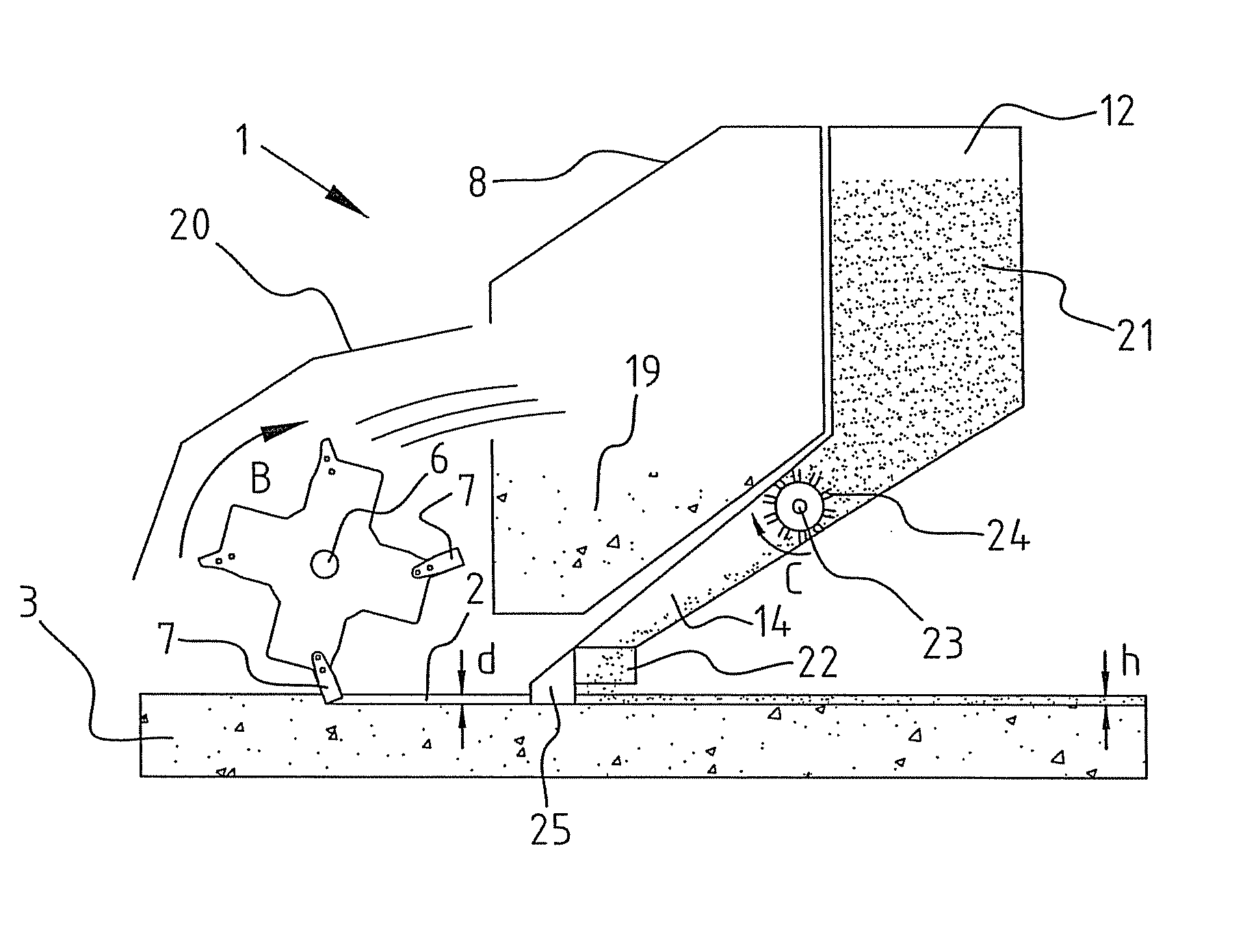
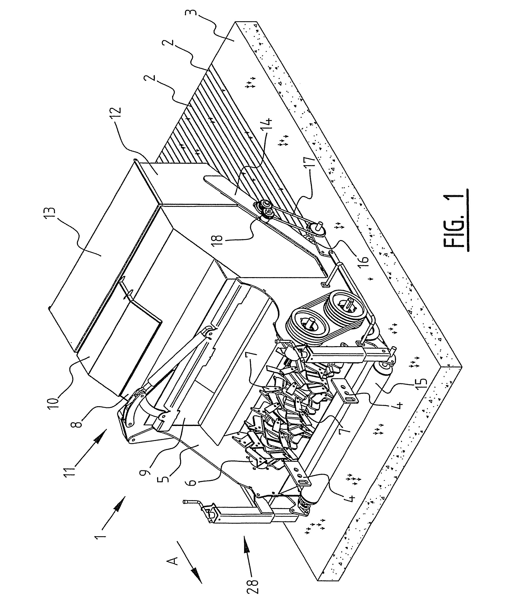
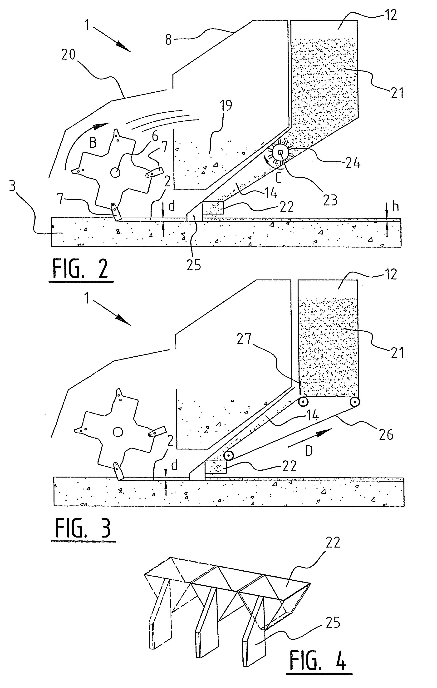
[0029]FIG. 1 shows a device according to the invention 1 with which slits 2 can be cut in a turf cover 3 forming a surface. Device 1 is attached by means of fixing eyes 4 to a pulling vehicle (not shown) which displaces device 1 over turf cover 3 in the direction of arrow A. Device 1 has a frame 5 with a rotatable shaft 6 on this frame 5. Blades 7 forming the cutter are arranged on rotatable shaft 6 for cutting slits 2 in turf cover 3. The distance between the frame and the surface, and thereby the depth d of the slit which is cut by the cutter during use, can be adjusted by means of height adjustment 28. Behind blades 7 the device 1 has a collecting bin 8 forming collecting means, with a collecting opening 9 and collecting bin cover 10 for collecting the material cut from turf cover 3 by means of blades 7. A hood (not shown) can be arranged over rotatable shaft 6 and blades 7, whereby during use the material thrown up by means of blades 7 is guided in the direction of collecting bi...


PUM


Abstract

The invention relates to a device for cutting slits in a surface, for instance a turf cover, comprising a frame displaceable over the surface, a movable cutter on the frame and oriented during use toward the surface for the purpose of cutting slits in the surface. The invention is distinguished in that the device comprises collecting means for collecting the material cut from the surface by means of the cutter.The invention also relates to a dispensing device, comprising a filler material container, a channel to an outflow opening oriented toward a slit, which channel is connected to the filler material container, and a dispensing mechanism in at least one of the channel and the filler material container.

Description

BACKGROUND OF THE INVENTION[0001]The invention relates to a device for cutting slits in a surface, for instance a turf cover, comprising a frame displaceable over the surface, a movable cutter on the frame and oriented during use toward the surface for the purpose of cutting slits in the surface.[0002]Such devices are known for aerating a turf cover, wherein slits are cut into the turf cover, for instance in order to remove dead grass and moss from the turf cover and thereby enhance growth of the turf cover. The known art has drawbacks. When the slits are cut in the turf cover, the material that has been cut away is left on the turf cover. In addition to the fact that this material which has been cut away and left behind can inhibit the growth of the grass, this material adversely affects the performance characteristics of the turf cover in the case of for instance playing fields. On golf courses material on the turf cover is particularly undesirable, for instance on the green, wher...

Claims


Application Information

Patent Timeline
Patent Type & Authority Patents(United States)
IPC IPC(8): A01B45/04
CPCA01B45/026
Inventor KRAAIJEVELD, TEUNIS JAN WILLEM
Owner GEBRR KRAAIJEVELD
Why Eureka
Try Eureka