
Power transmission device

a technology of power transmission device and limiter, which is applied in the direction of couplings, mechanical devices, slip couplings, etc., can solve the problems of /b> interference with the pulley, the limiter cannot work, and the power transmission cannot be interrupted, etc., and achieve the effect of reliably interrupting the power transmission

Inactive Publication Date: 2008-10-02
DENSO CORP
View PDF2 Cites 0 Cited by
  • Summary
  • Abstract
  • Description
  • Claims
  • Application Information

AI Technical Summary

Benefits of technology

[0014]The present invention has been made to solve the above-mentioned problems and provides a power transmission device that can prevent an adapter from being re-press-fitted around an input shaft, and therefore, can reliably interrupt power transmission when torque reaches a predetermined level.
[0016]In this power transmission device, even if excessive torque is applied and a large axial force is applied to the power interruption member (113) on the adapter (83), so long as the adapter (83) and the spacer (69) do not slip with respect to each other, the axial force is not affected to the adapter (83), and therefore, in contrast to the conventional art, re-press-fitting of the press-fitted adapter can be prevented. Further, when excessive torque is applied, even if the adapter (83) and the inner circumference (101) of the hub (99) start to slip with respect to each other, the adapter (83) and the spacer (69) do not slip with respect to each other, and therefore, the relative rotation between the adapter (83) and the power interruption member (113) can be reliably caused to break the power interruption member (113).
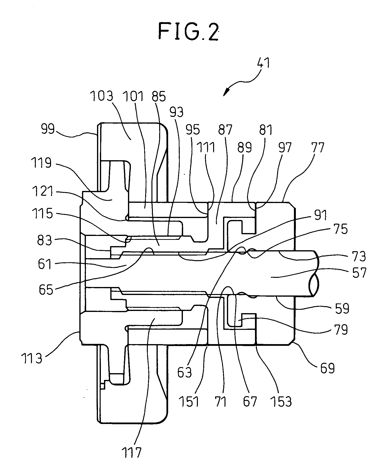
[0017]Further, according to the present invention, assuming that an abutment surface (151) between the adapter (83) and the inner circumference (101) of the hub (99) has an equivalent friction diameter dw1 and a friction coefficient μw1 and an abutment surface (153) between the adapter (83) and the spacer (69) has an equivalent friction diameter dw2 and a friction coefficient μw2, if dw1 and dw2 are substantially comparable to each other, a relationship μw1<μw2 may be established. Therefore, even if the equivalent friction diameters are comparable to each other, when excessive torque is applied, abutment surface (153) can be prevented from slipping before the abutment surface (151) and the power interruption mechanism can work properly.
[0019]Still further, according to the present invention, a washer (203) may be disposed between the adapter (83) and the spacer (69). Therefore, even if the perpendicularity and flatness of the rear-side adapter bearing surface of the adapter (83) with respect to the axis line is somewhat uneven, or perpendicularity and flatness of the front-side bearing surface of the spacer (69) with respect to the axis line is somewhat uneven, the washer (203) can absorb the unevenness, and therefore, damage and wear of the parts due to an unbalanced load, partial contact and the like can be prevented.
[0020]Still further, according to the present invention, assuming that an abutment surface (151) between the adapter (83) and the inner circumference (101) of the hub (99) has an equivalent friction diameter dw1 and a friction coefficient μw1, a contact surface (207) between the adapter (83) and the washer (203) has an equivalent friction diameter dw3 and a friction coefficient μw3, and a contact surface (211) between the washer (203) and the spacer (69) has an equivalent friction diameter dw4 and a friction coefficient μw4, when dw1, dw3 and dw4 are substantially comparable to each other, a relationship μw1<μw3 and μw1<μw4 may be established. Therefore, even if the equivalent friction diameters dw1, dw3 and dw4 are comparable to each other, when excessive torque is applied, the contact surfaces (207, 211) can be prevented from slipping before the abutment surface (151) and the power interruption mechanism can work properly.
[0021]Still further, according to the present invention, an abutment surface (311) between the adapter (83) and the spacer (69) may be tapered. Therefore, when an excessive axial force is applied due to seizure of a compressor and the like, the tapered surfaces are strongly fitted into each other to increase binding force and, due to a wedge effect of the tapered surfaces, unevenness of the abutment surface can be corrected and occurrence of the unbalanced load can be prevented.

Problems solved by technology

When the re-press-fitting occurs in this portion, as shown in Japanese Unexamined Patent Publication No. 2003-35255, an axial tensile force to be applied to the power interruption member 29 dissipates, and therefore, there is a problem in that, even though the torque exceeds a predetermined level, a limiter does not work and the power transmission cannot be interrupted.
Therefore, there is another problem in that the hub 33 presses the pulley 17 rearward to apply a thrust load to the bearing 15 so as to significantly reduce durability of the bearing.
Still further, for example, in a construction in which the hub 33 is engaged with the pulley 17 via an elastic member, there is yet another problem in that the hub 33 interferes with the pulley 17.

Method used


Image

  • Power transmission device
  • Power transmission device
  • Power transmission device

Examples


Embodiment Construction

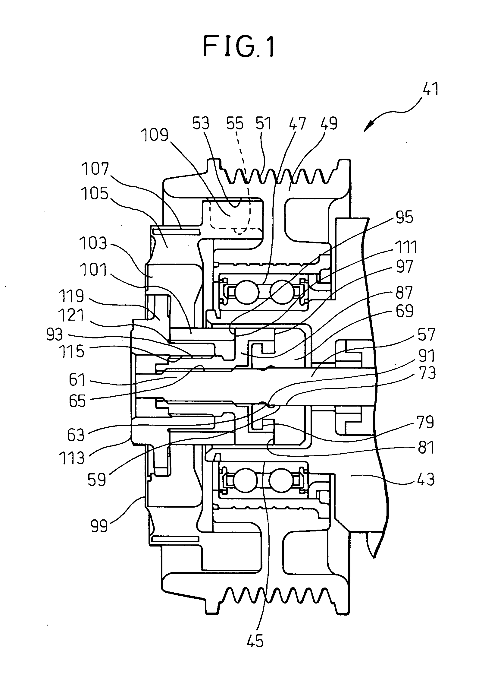
[0045]Hereinafter, the embodiments of the present invention will be described with reference to FIGS. 1-18.

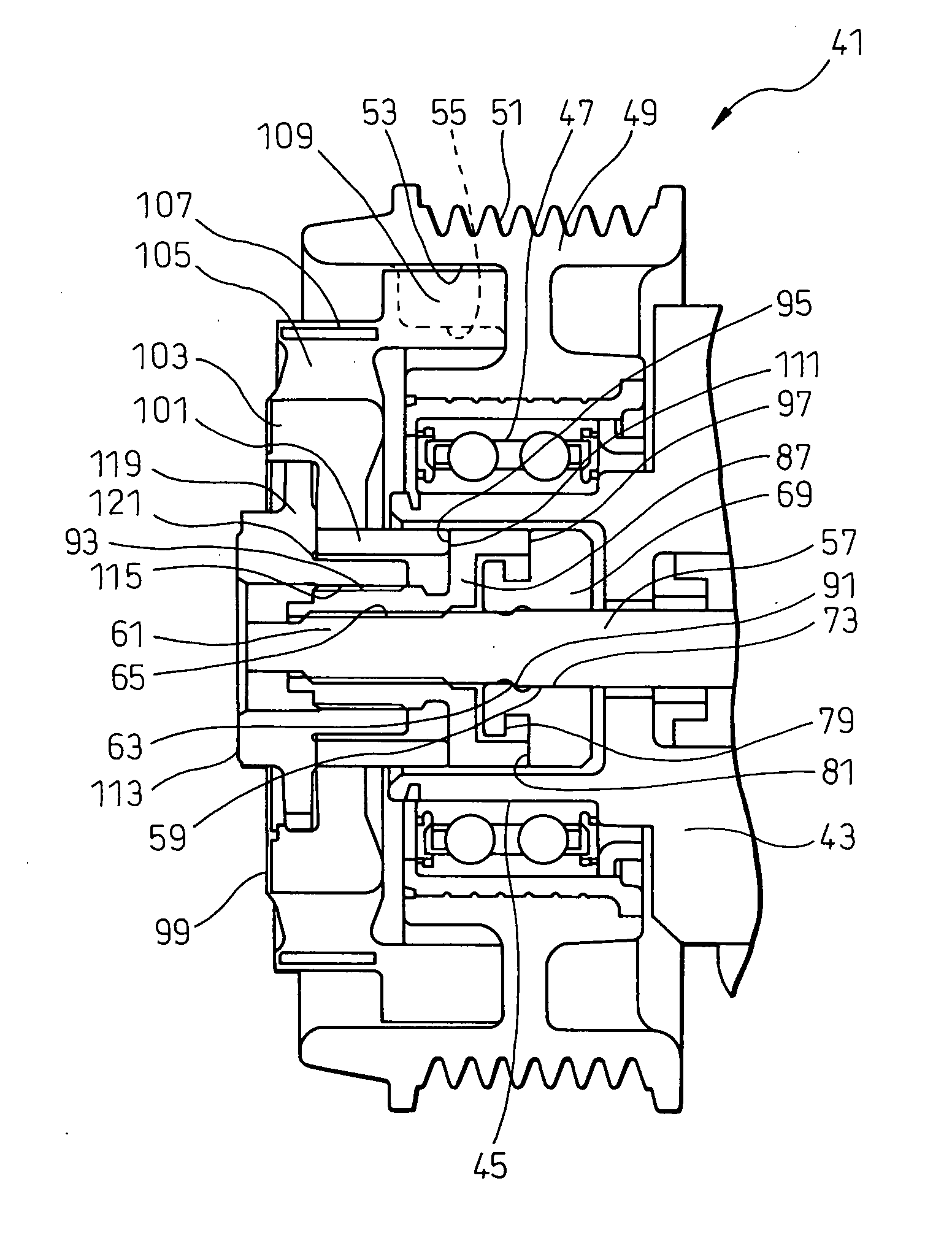
[0046]FIGS. 1 and 2 show a power transmission 41 that is a first embodiment of the present invention. The power transmission device 41 is attached to a compressor housing 43 and a tubular bearing support section 45 is provided at a front side of the housing 43. A pulley 49 is supported on an outer circumference of the bearing support section 45 via a radial bearing 47. A belt groove 51 is formed on an outer circumference of the pulley 49 and a belt is wound around the belt groove 51 so that rotational torque is transmitted from a vehicle engine and the like. An annular pocket 53 is formed at a front side of the pulley 49, and a pulley-side engagement section 55 that has concaves and convexes in a radial direction is formed on an inner circumferential surface of the annular pocket 53.

[0047]On the other hand, an input shaft 57 that transmits power to the compressor within the hou...


PUM


Abstract

A power transmission device 41, in which a spacer 69 is press-fitted around a rear side of a male thread section 63 of an input shaft 57. An adapter 83 is screwed to the male thread section 63 of the input shaft 57 and its large diameter section 89 abuts against a large diameter section 77 of the spacer 69. A hub 99 abuts against a front side of the large diameter section 89 of the adapter 83. A power interruption member 113 has a flange section 119 abutting against the hub 99, and a tubular section 117 screwed to an outer circumference of the adapter 83. It is configured so that a friction coefficient μw1 between the large diameter section 89 of the adapter 83 and an inner circumference of the hub 99 is smaller than a friction coefficient μw2 between the large diameter section 89 of the adapter 83 and the large diameter section 77 of the spacer 69. The adapter is re-press-fitted around the adapter so that when excessive torque occurs, power transmission can be reliably interrupted when torque reaches a predetermined level.

Description

BACKGROUND OF THE INVENTION[0001]1. Field of the Invention[0002]The present invention relates to a power transmission device that transmits power from an external power source to a driven apparatus and that has a torque limiter.[0003]2. Description of the Related Art[0004]Typically, a compressor for an automobile air conditioner that receives power transmitted from an external power source such as an engine and the like via a belt, a pulley and the like is provided with a power transmission device that is disposed between the belt and an input shaft of the compressor and that can interrupt the power when excessive torque occurs.[0005]As an example of the power transmission device of this type, a known power transmission device is disclosed in Japanese Unexamined Patent Publication No. 2006-292042 and it is shown in FIGS. 19 and 20. This power transmission device 11 has: a pulley 17 that is rotatably mounted on a compressor housing 13 via a bearing 15; and an input shaft 19 that is s...

Claims


Application Information

Patent Timeline
Patent Type & Authority Applications(United States)
IPC IPC(8): F16D7/02
CPCF16D7/021F16D7/028
Inventor NOSAKA, MICHIYASUTADA, YOSHIKI
Owner DENSO CORP
Learn More