
Power Transmission Device

Inactive Publication Date: 2008-11-20
TOYOTA JIDOSHA KK
View PDF7 Cites 2 Cited by
  • Summary
  • Abstract
  • Description
  • Claims
  • Application Information

AI Technical Summary

Benefits of technology

[0016]In addition to the above advantageous effects, the route of the fluid can be switched between the first flow route and the second flow route, by controlling the fluid suction condition or a fluid discharging condition of the positive displacement pump. Here, in case the first flow route is selected, a power to rotate the output member in the forward direction is established. Alternatively, in case the second flow route is selected, a power to rotate the output member in the backward direction is established. That is, the power transmission can be carried out in different rotational directions of the output member in case of driving the output member by the fluid discharged from the positive displacement pump.
[0017]Also, a component force according to the kinetic energy of the case in which the fluid flows along a blade, or of the case in which the fluid collides against the blade, is transmitted to the output member and the output member is thereby rotated.
[0018]As explained above, the amount of the fluid fed from the positive displacement pump to the output member in the direction to rotate the output member backwardly is reduced in case the route of rotating the output member in the forward direction is selected. Therefore, an increase in a kinetic energy to rotate the output member backwardly is restrained. For this reason, the power transmission in the direction to rotate the output member backwardly can be interrupted certainly.
[0019]In addition to above, according to the invention, the power of the prime mover is transmitted to the input member to drive the positive displacement pump. It is also possible to rotate the output member in the forward direction by connecting the connecting member selectively with the output member to transmit the power from the input member.
[0020]In case the flow route of rotating the output member in the backward direction by the fluid discharged from the positive displacement pump is selected, moreover, the power transmission to rotate the output member in the forward direction can be interrupted certainly.
[0021]In case the flow route of rotating the output member in the backward direction by the fluid discharged from the positive displacement pump is selected, still moreover, the fluid discharged from the positive displacement pump is jetted onto the output member, and the power transmission to rotate the output member in the forward direction can be interrupted certainly.

Problems solved by technology

However, according to the power transmission system disclosed in Japanese Patent Laid-Open No. 8-109955, a rotational direction of the output shaft cannot be changed.

Method used


Image

  • Power Transmission Device
  • Power Transmission Device
  • Power Transmission Device

Examples


embodiment 1

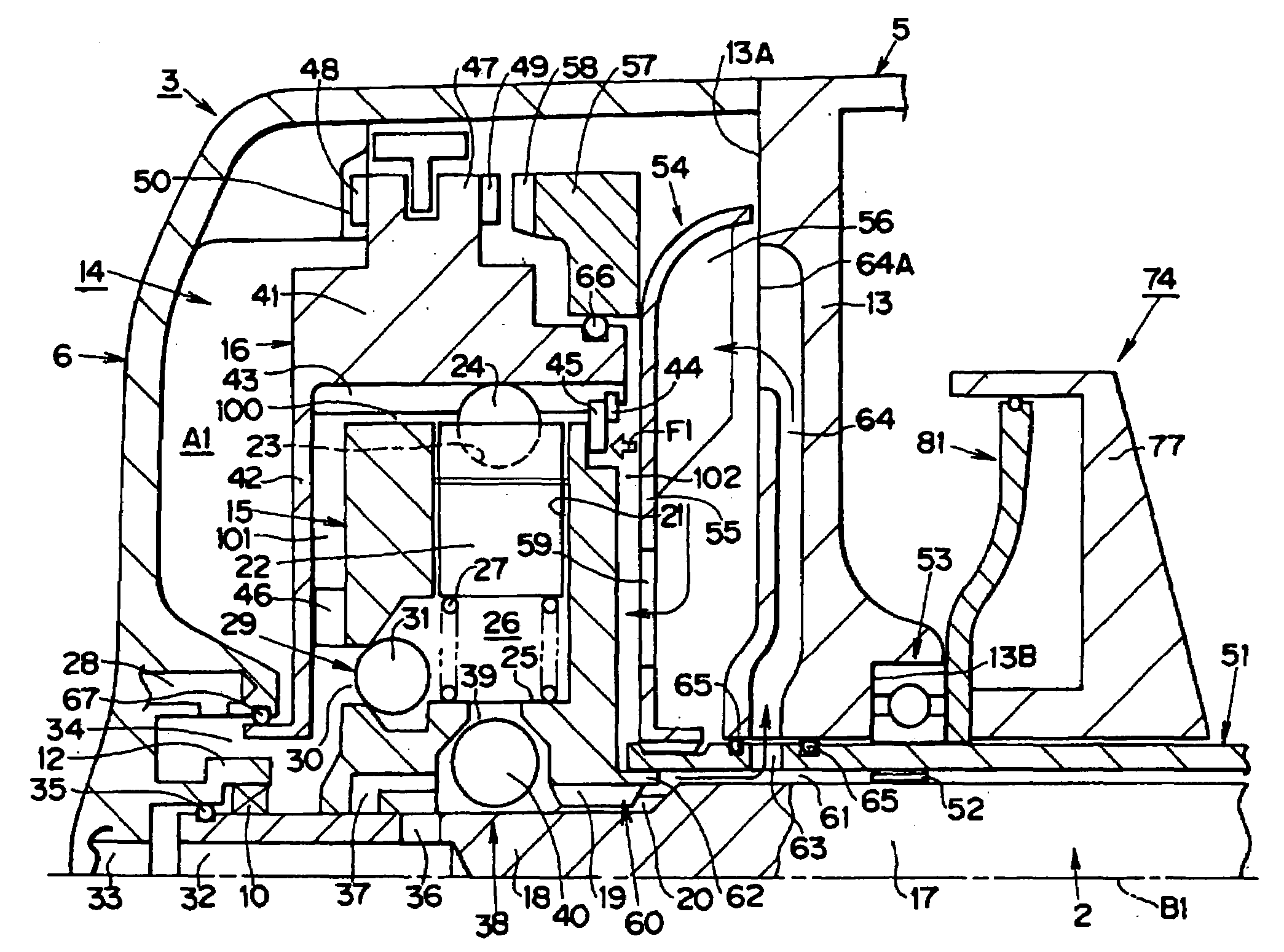
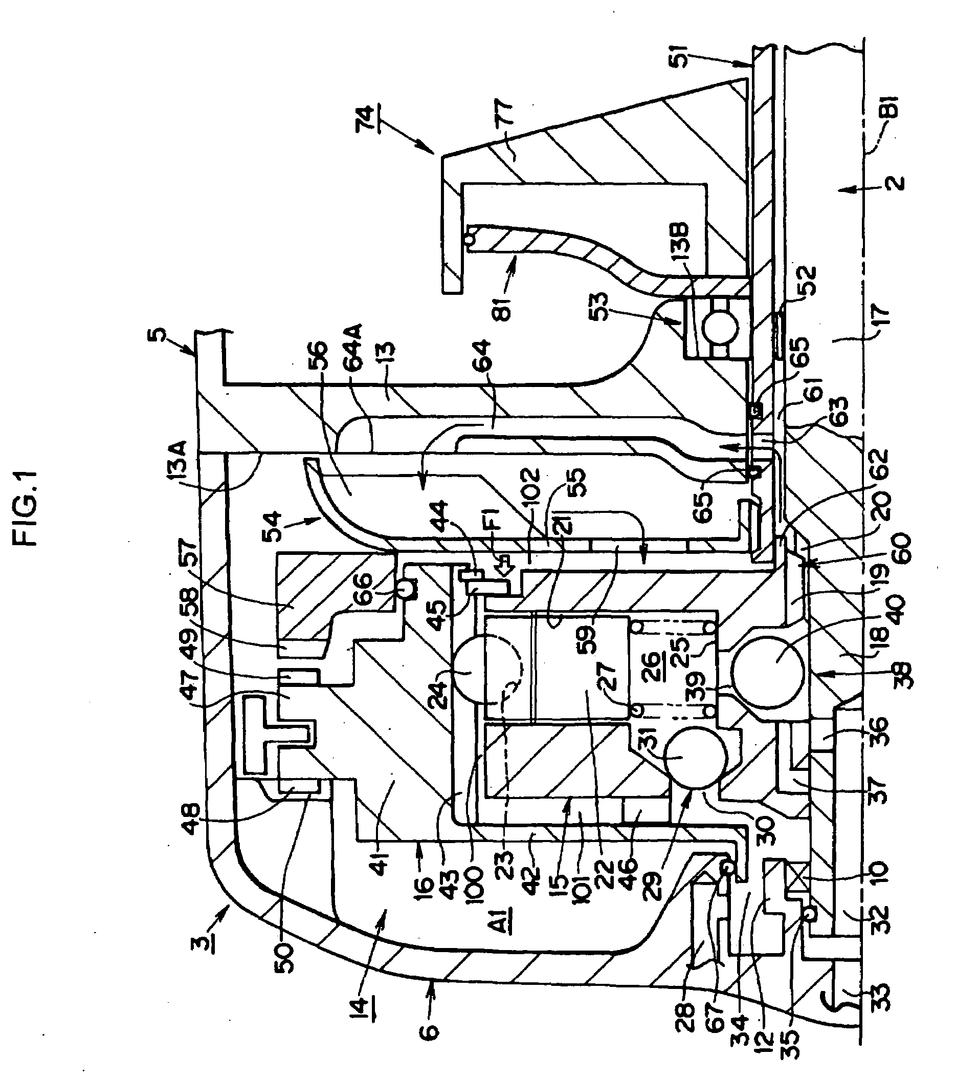
[0032]Here will be explained an example of a configuration of the radial piston pump 14 employed in the embodiment 1 with reference to FIG. 1. The radial piston pump 14 comprises an inner race 15 and an outer race 16. The inner race 15 is mounted on the input shaft 2. In other words, the inner race 15 is formed annularly around a center axis B1 of the input shaft 2. The input shaft 2 comprises a diametrically large portion 17, and a diametrically small portion 18 on which the inner race 15 is mounted. There are formed internal teeth 19 on an inner circumference of the inner race 15, and external teeth 20 on an outer circumference of the diametrically small portion 18 of the input shaft 2. Here, the internal teeth 19 and the external teeth 20 are meshed with each other. That is, the input shaft 2 is splined to the inner race 15 so as to rotate integrally with the inner race 15 around an axis B1. Additionally, the inner race 15 is movable on the input shaft 2 in the axial direction.

[0...

embodiment 2

[0071]Next, here will be explained another example of a configuration of the radial piston pump 14 with reference to FIG. 4. In FIG. 4, the oil passages 60 and 61 are situated inward of the oil passage 102, i.e., closer to the axis B1. On the other hand, the oil passage 59 is situated outward of the oil passages 60 and 61. Additionally, a side face 103 of the inner race 15 is tapered outwardly to enlarge the flowing area of the oil passage 102. Specifically, a clearance in the axial direction between a side face of the plate 55 and the side face 103 of the inner race 15 is widened outwardly. In other words, a wall thickness of the inner race 15 is thinned toward outside in the axial direction. The remaining structures of the Embodiment 2 are identical to those of the Embodiment 1.

[0072]According the Embodiment 2, the advantages achieved by the Embodiment 1 can also be achieved by the structures of the Embodiment 2 identical to those of Embodiment 1. In addition, according to the Emb...

embodiment 3

[0074]Here will be explained an example of a configuration of the radial piston pump 14 in the Embodiment 3 with reference to FIGS. 5 and 6. FIG. 5 is a view showing a cross-section including the axis B1, and FIG. 6 is a view partially showing a circumferential cross-section of the radial piston pump 14. As shown in FIG. 5, a bearing 200 is press-fitted into an inner circumference of the input shaft 2 at an end portion of a rear case 6 side. On an inner wall of the rear case 6, there is formed a sleeve 201, and the bearing 200 is held by the sleeve 201. Also, an oil passage 33 is formed in the rear case 6 in the axial direction along the sleeve 201. Meanwhile, an oil passage 202 is formed in the input shaft 2, and an oil passage 203 is opened on an outer circumference of the input shaft 2. Further, a sealing member 204 is provided to seal a clearance between the sleeve 201 and the input shaft 2 liquid-tightly. The oil passage 33 is thus connected to the oil passage 203 through the o...


PUM


Abstract

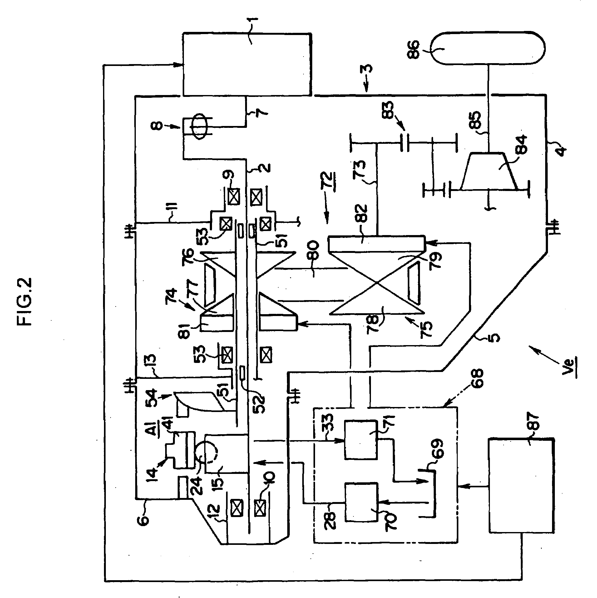
A power transmission system having a positive displacement pump which is driven by a prime mover, and an output member which is driven by a fluid discharged from the positive displacement pump, characterized by comprising a rotational direction switching mechanism for switching a rotational direction of the output member between forward direction and backward direction. The rotational direction switching mechanism comprises a mechanism for switching a direction of a torque applied to the output member through the fluid between forward direction and backward direction.

Description

TECHNICAL FIELD[0001]This invention relates to a power transmission system, in which an output member can be rotated by a fluid discharged from a positive displacement pump.BACKGROUND ART[0002]In general, a vehicle is provided with a prime mover and a power transmission system is arranged on an output side of the prime mover. This power transmission system comprises a clutch, a transmission and so on. An engaging type power transmission system, a frictional type power transmission system, a fluid type power transmission system, an electromagnetic type power transmission system etc. are known in the art, and one example of the fluid type power transmission system is disclosed in Japanese Patent Laid-Open No. 8-109955. According to the high hydraulic jet transmission taught by Japanese Patent Laid-Open No. 8-109955, a positive displacement high pressure hydraulic pump is driven by a prime mover, and the oil discharged from the hydraulic pump is introduced selectively into two nozzles ...

Claims


Application Information

Patent Timeline
IPC IPC(8): F16H61/30F16D31/02F16D33/00
CPCF16D11/10F16D31/02F16D33/00F16D39/00F16H9/18F16H55/56
Inventor SHIOIRI, HIROYUKIHOJO, YASUOIBARAKI, RYUJINOMASA, HITOSHI
Owner TOYOTA JIDOSHA KK
Learn More