
Bipolar DC power transmission scheme

a power transmission scheme and bipolar technology, applied in the field of bipolar dc power transmission scheme, can solve the problems of increasing the risk of damage to the converters connected to the healthy dc pole, interfering with power transmission operation,

Active Publication Date: 2020-06-02
GENERAL ELECTRIC TECH GMBH
View PDF14 Cites 1 Cited by
  • Summary
  • Abstract
  • Description
  • Claims
  • Application Information

AI Technical Summary

Benefits of technology

The patent describes a power transmission device that can control the movement of power in a more efficient and safe way. By adding a controller and monitoring device to the device, it can detect and isolate faults that might occur in the system. This helps to minimize power interruption and allows certain parts of the system to continue operating safely. The monitoring device can also identify which part of the system has the fault, reducing the risk of incorrect identification. The controller can initiate the de blocking of certain converters at specific power levels or when certain conditions are met, ensuring a smooth transition during operation. Overall, the patent provides a solution for improving the reliability and safety of power transmission devices.

Problems solved by technology

Although the healthy DC pole is normally expected to be unaffected by the fault and thereby able to continue transmitting power, the inventors have found that the mutual coupling between the faulty and healthy DC poles may result in strong dynamics in the converters connected to the healthy DC pole that leads to overcurrent and / or overvoltage, which not only interferes with the power transmission operation but also increases the risk of damage to the converters connected to the healthy DC pole.

Method used


Image

  • Bipolar DC power transmission scheme
  • Bipolar DC power transmission scheme
  • Bipolar DC power transmission scheme

Examples


Embodiment Construction

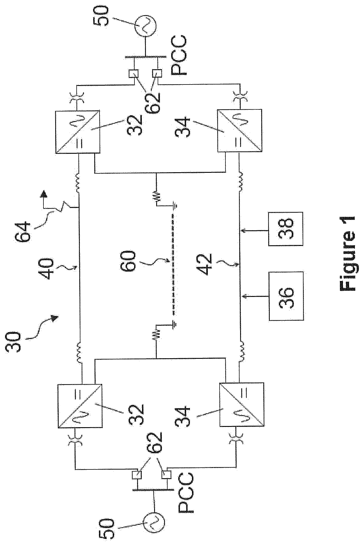
[0035]A bipolar DC power transmission scheme according to an embodiment of the invention is shown in FIG. 1 and is designated generally by the reference numeral 30.

[0036]The bipolar DC power transmission scheme 30 comprises first and second DC poles, a plurality of first converters 32, a plurality of second converters 34, a controller 36 and a monitoring device 38.

[0037]For the purposes of simplicity, the bipolar DC power transmission scheme 30 of FIG. 1 is described with reference to a controller 36 based on a single control unit and a single monitoring device 38. As explained above, a plurality of control units may be used in placed of the single control unit, and a plurality of monitoring devices may be used in place of the single monitoring device 38.

[0038]The first DC pole includes a first DC power transmission line 40 extending between first and second ends. The second DC pole includes a second DC power transmission line 42 extending between first and second ends.

[0039]Each co...


PUM


Abstract

A bipolar DC power transmission scheme comprises: DC poles, each including a respective power transmission medium extending between two ends; a plurality of converters, wherein each end of the power transmission medium of the first pole is respectively operatively connected to a converter, and each end of the power transmission medium of the second pole is respectively operatively connected to a converters; a controller programmed to block one or more of the converters in response to a fault occurring on either of the first and second poles; and a monitoring device configured to identify the faulty poles on which the fault has occurred, wherein the controller is further programmed to deblock the or each blocked converter connected to the other of the poles after the monitoring device has identified the faulty one of the poles on which the fault has occurred.

Description

FIELD OF INVENTION[0001]This invention relates to a bipolar DC power transmission scheme and a method of operating a bipolar DC power transmission scheme.BACKGROUND OF THE INVENTION[0002]It is known to use a bipolar DC power transmission scheme to transmit power at high voltage levels over long distances.BRIEF DESCRIPTION OF THE INVENTION[0003]According to a first aspect of the invention, there is provided a bipolar DC power transmission scheme comprising: first and second DC poles, each DC pole including a respective DC power transmission medium extending between two ends; a plurality of first converters and a plurality of second converters, wherein each end of the DC power transmission medium of the first DC pole is respectively operatively connected to at least one of the plurality of first converters, and each end of the DC power transmission medium of the second DC pole is respectively operatively connected to at least one of the plurality of second converters; a controller pro...

Claims


Application Information

Patent Timeline
Patent Type & Authority Patents(United States)
IPC IPC(8): H02H7/26G01R19/14H02J3/36H02H3/06G01R31/50H02M1/32H02M5/458H02H3/16
CPCH02H3/06H02J3/36G01R19/14G01R31/50H02H7/268H02H3/063H02M5/4585Y02E60/60H02H3/16H02M1/32G01R31/52H02J1/00
Inventor GUPTA, ROBINWHITEHOUSE, ROBERT STEPHEN
Owner GENERAL ELECTRIC TECH GMBH
Learn More