
Running control system for vehicle

a control system and vehicle technology, applied in the field of control systems, can solve the problems of increasing the amount of shock caused by reducing the inability to apply engine braking force to the drive wheels, and the inability to reduce the longitudinal acceleration of the vehicle, so as to reduce the uncomfortable feeling

Active Publication Date: 2017-03-28
TOYOTA JIDOSHA KK
View PDF73 Cites 1 Cited by
  • Summary
  • Abstract
  • Description
  • Claims
  • Application Information

AI Technical Summary

Benefits of technology

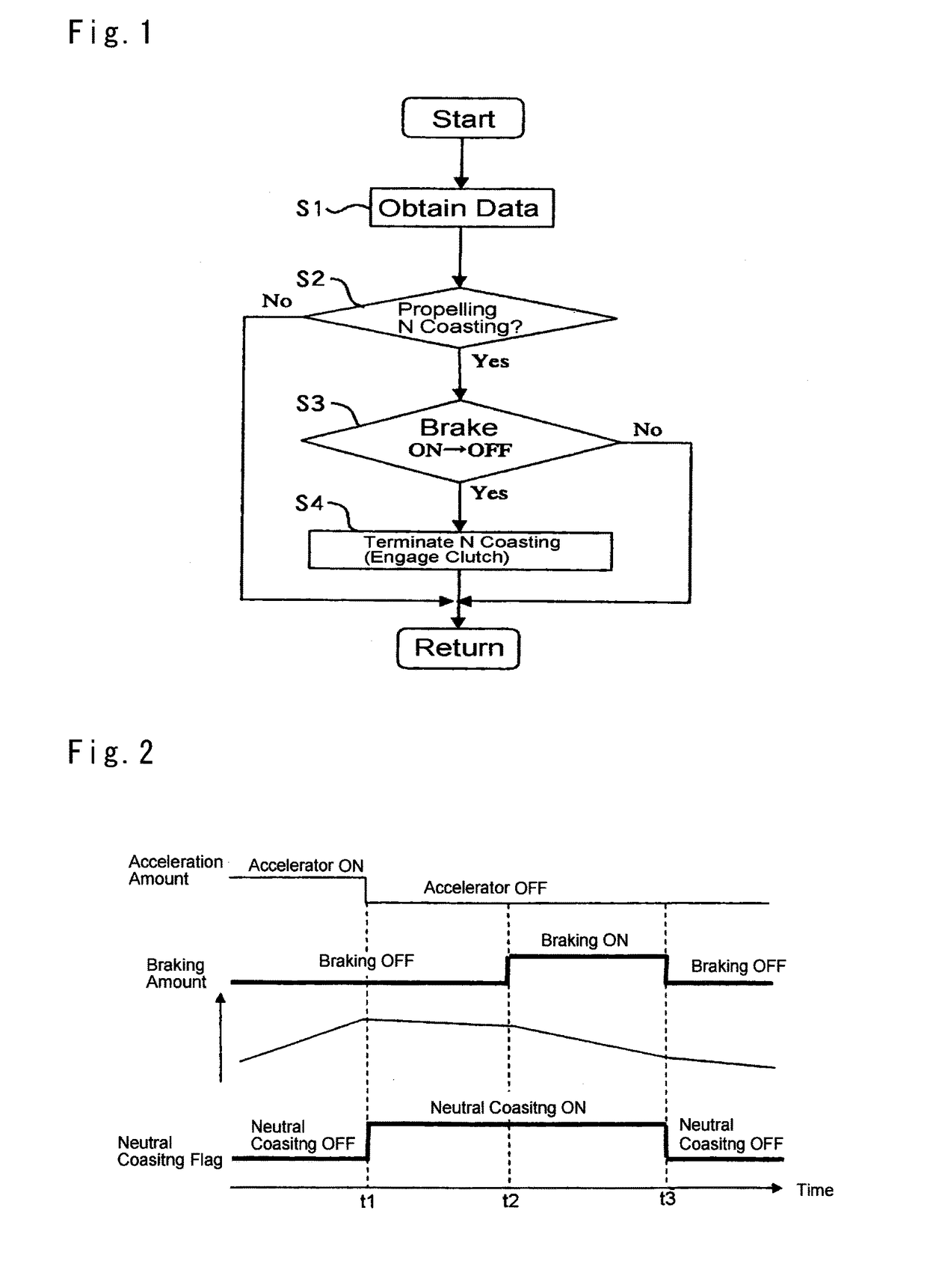
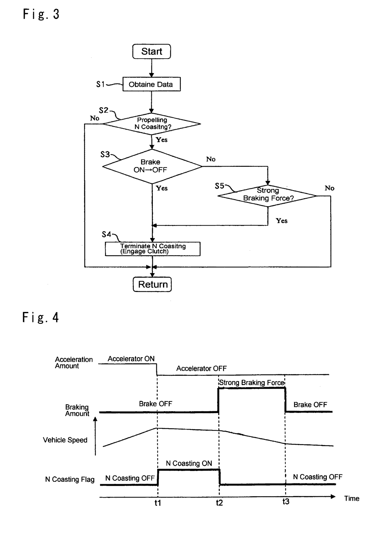
The present invention aims to provide a running control system that can adjust the braking force to reduce uncomfortable feelings during coasting while disengaging a clutch. This system allows the vehicle to coast while the prime mover is inactivated or operating at an idling speed, resulting in improved fuel economy. The braking force can be applied to the drive wheels without excess or deficiency, reducing braking shocks. Additionally, when the deceleration demand is eliminated, the braking force of the prime mover can be applied instead of the braking force of the braking device, preventing unintentional increment of acceleration.

Problems solved by technology

In this case, however, an engine braking force cannot be applied to the drive wheels.
This means that a braking force would be applied to the vehicle more than expected, and consequently, shocks resulting from reducing longitudinal acceleration of the vehicle would be caused frequently.

Method used


Image

  • Running control system for vehicle
  • Running control system for vehicle
  • Running control system for vehicle

Examples


Embodiment Construction

)

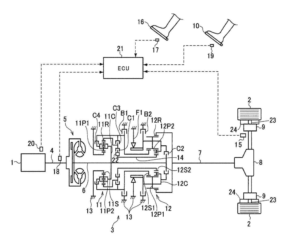
[0020]Next, preferred examples of the running control system of the present invention will be explained. Referring now to FIG. 5, there is shown a preferred example of a structure of the vehicle to which the present invention is applied. In the powertrain shown in FIG. 5, a geared transmission 3 is disposed between an internal combustion engine (as will be called the “engine” hereinafter) 1 and drive wheels 2, and the geared transmission 3 is adapted to establish eight forward stages and one reverse stage. For example, a gasoline engine, a diesel engine and etc. may be used as the engine 1. A fluid coupling (as will be called the “torque converter” hereinafter) 5 having torque multiplying function is connected to an output shaft 4 of the engine 1, and the geared transmission 3 is connected to an output shaft 6 of the torque converter 5. The drive wheels 2 are connected to an output shaft 7 of the geared transmission 3 through a differential gear unit 8. The powertrain shown in FIG....


PUM


Abstract

A running control system for vehicles is provided to reduce uncomfortable feeling during coasting by adjusting a braking force. The running control system is applied to a vehicle having a braking device adapted to generate a braking force according to an operation of a driver irrespective of an engagement state of the engagement elements disposed between a prime mover and drive wheels. The running control system comprises a controller that applies a braking force of the prime mover to the drive wheels by bringing the engagement elements into engagement to enable torque transmission between the prime mover and the drive wheels, when the braking force of the braking device is eliminated by aborting an operation of the braking device during coasting while disengaging the engagement elements to interrupt torque transmission between the prime mover and the drive wheels.

Description

TECHNICAL FIELD[0001]The present invention relates to a control system for controlling a driving force and a braking force during propelling a vehicle, and more particularly, to a running control system for controlling a coasting of the vehicle.BACKGROUND ART[0002]A prime mover of vehicle such as an internal combustion engine is adapted not only to generate a driving force for propelling the vehicle but also to generate a power for electric generation, air conditioning etc. To this end, the engine has to be activated even if the vehicle is stopping. Basically, the engine is started by a motor (i.e., a cranking). In order to allow the engine to be activated while the vehicle is stopping, a vehicle is provided with a clutch for disconnecting the engine from a gear train and drive wheels. Such clutch is brought into disengagement not only when the vehicle is stopping but also when the engine is not generating the driving force during running. If the clutch is brought into disengagement...

Claims


Application Information

Patent Timeline
Patent Type & Authority Patents(United States)
IPC IPC(8): B60W30/18F16D48/02B60W10/18B60W10/115
CPCB60W30/18136B60W10/115B60W10/18B60W30/18072F16D48/02B60W2030/1809Y10T477/647B60W10/184B60W10/02Y02T10/60
Inventor KIM, JONGGAP
Owner TOYOTA JIDOSHA KK
Learn More