
Vehicle power transmission device

a technology for transmission devices and vehicles, applied in fluid gearings, gearing details, gearing, etc., can solve problems such as difficult rotation and complicated control, and achieve the effect of suppressing complication and suppressing shock

Inactive Publication Date: 2020-08-06
TOYOTA JIDOSHA KK
View PDF0 Cites 2 Cited by
  • Summary
  • Abstract
  • Description
  • Claims
  • Application Information

AI Technical Summary

Benefits of technology

The vehicle power transmission device described in this patent allows for both forward and reverse traveling using the same power source. This is achieved by switching the mode-switching clutch between one-way mode and free mode to prevent interference between the power transmission paths. The speed ratio in the first power transmission path is larger than the maximum speed ratio of the second power transmission path, so that power transmission is interrupted during the switching transition period. This prevents shocks and simplifies the control mechanism during the switching transition period. The vehicle power transmission device provides a compact and efficient solution for power transmission in electric vehicles.

Problems solved by technology

Therefore, torque capacities of the first clutch and the second clutch need to be precisely controlled, which makes the control complicated.
At this time, if the mode-switching clutch is switched to the one-way mode, the input element and the output element interfere with each other, thereby making the rotation difficult.

Method used


Image

  • Vehicle power transmission device
  • Vehicle power transmission device
  • Vehicle power transmission device

Examples


Embodiment Construction

[0023]Hereinafter, embodiments of the present disclosure will be described in detail with reference to the drawings. In the embodiments below, the drawings are appropriately simplified or modified, and respective dimensional ratios, shapes, and the like of the components are not necessarily drawn accurately.

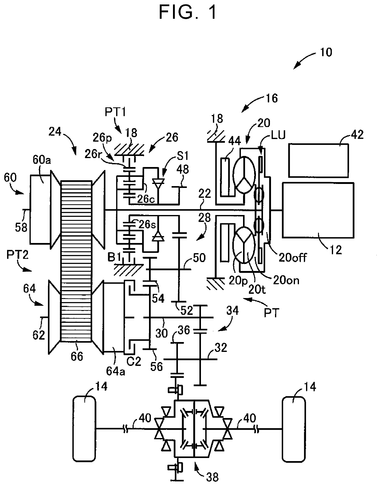
[0024]FIG. 1 is a skeleton diagram illustrating a schematic configuration of a vehicle 10 to which the present disclosure is applied. In FIG. 1, the vehicle 10 includes a vehicle power transmission device 16 (hereinafter, referred to as a power transmission device 16) that transmits power output from an engine 12 functioning as a power source to driving wheels 14.

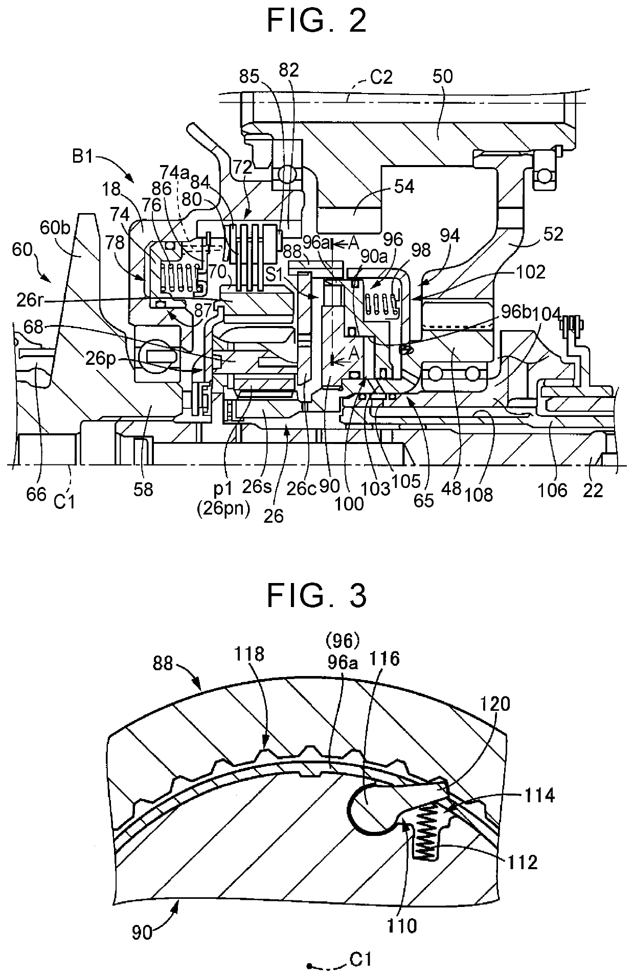
[0025]The power transmission device 16 is provided between the engine 12 and the driving wheels 14. The power transmission device 16 includes, in a case 18 serving as a non-rotating member, a known torque converter 20, an input shaft 22, a continuously variable transmission 24, a forward / reverse switching device 26, gear...


PUM


Abstract

A vehicle power transmission device includes: an input shaft; an output shaft; a first power transmission path configured to transmit power between the input shaft and the output shaft; and a second power transmission path configured to transmit power between the input shaft and the output shaft. The first power transmission path includes a mode-switching clutch configured to be switched between a one-way mode and a free mode, the one-way mode being a mode in which power acting in a forward rotation direction is transmitted while power acting in a reverse rotation direction is interrupted, and the free mode being a mode in which power acting in the forward rotation direction and power acting in the reverse rotation direction are interrupted. The second power transmission path includes a control clutch configured such that a torque capacity of the control clutch is controllable.

Description

INCORPORATION BY REFERENCE[0001]The disclosure of Japanese Patent Application No. 2019-016423 filed on Jan. 31, 2019 including the specification, drawings and abstract is incorporated herein by reference in its entirety.BACKGROUND1. Technical Field[0002]The present disclosure relates to a vehicle power transmission device that includes a first power transmission path and a second power transmission path provided in parallel between an input shaft and an output shaft.2. Description of Related Art[0003]Japanese Patent No. 5765485 (JP 5765485 B) describes a vehicle power transmission device that includes a first power transmission path and a second power transmission path provided in parallel between an input shaft and an output shaft. In the power transmission device described in JP 5765485 B, a gear train and a first clutch are provided in the first power transmission path, and a continuously variable transmission and a second clutch are provided in the second power transmission path...

Claims


Application Information

Patent Timeline
Patent Type & Authority Applications(United States)
IPC IPC(8): F16H3/10F16H57/04
CPCF16H2037/026F16H57/0489F16H3/10F16H2061/6608F16H9/04F16H37/021F16H37/0813F16H37/0826F16H41/04F16H47/065F16H47/08F16H59/02F16H61/04F16H2061/0448F16H2200/203F16D41/14F16H37/022
Inventor OHGATA, YUSUKEOITA, SHINJINITANI, HIROMITSUFUJIKAWA, MEGUMIOISHI, YOSHIHIRO
Owner TOYOTA JIDOSHA KK
Learn More