
Braking system with combined function of drive-by-wire and power-assisting and with manpower-magnification action

An amplifying and compound function technology, applied in the direction of brakes, brake transmissions, vehicle components, etc., can solve problems such as disadvantages, large size of vacuum boosters, uncontrollable booster size, etc., to achieve small system pressure fluctuations and reduce motor demand. , the effect of smooth switching process

Inactive Publication Date: 2015-06-17
JILIN UNIV
View PDF7 Cites 14 Cited by
  • Summary
  • Abstract
  • Description
  • Claims
  • Application Information

AI Technical Summary

Problems solved by technology

Although the traditional braking system has become a very mature technology, there are still some problems in this system: for example, the volume of the vacuum booster is relatively large, the size of the booster is uncontrollable, and it is impossible to cut off the connection between the brake and the human operation, so it affects to a certain extent braking energy recovery
Although various types of brake-by-wire systems have many advantages as mentioned above, they also have some disadvantages compared with non-control-by-wire systems: special failure backup devices need to be set up, which increases the complexity and cost of the system; Under certain conditions, the pedal force is always generated by the simulator, and the pedal force cannot be adjusted; the manpower applied to the brake pedal is not directly used to generate the braking force, which is not conducive to shortening the brake action time
At present, no brake system has been found that has the advantages of both non-wire brake system and wire brake system

Method used


Image

  • Braking system with combined function of drive-by-wire and power-assisting and with manpower-magnification action

Examples


Embodiment Construction

[0024] The specific implementation manner of the present invention will be described in detail below in conjunction with the accompanying drawings.

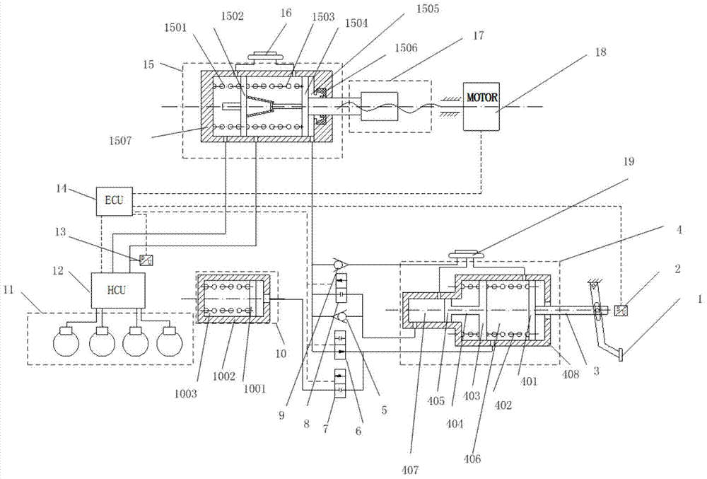
[0025] refer to figure 1 , a brake system with a manpower amplification function of wire control and power-assisted compound functions, including a brake pedal 1, a pedal displacement sensor 2, a push rod 3, a manpower cylinder 4, a first one-way valve 5, and a second one-way valve 9. Normally open solenoid valve 6, first normally closed solenoid valve 7, second normally closed solenoid valve 8, pedal simulator 10, wheel cylinder 11, hydraulic control unit 12, pressure sensor 13, electronic control unit 14, three-chamber main Cylinder 15, master cylinder liquid storage tank 16, manpower cylinder liquid storage tank 19, motion conversion and transmission mechanism 17, motor 18.

[0026] The brake pedal 1 is pin-connected to the push rod 3; the push rod 3 is connected to the rear piston 401 of the manpower cylinder 4; the manpower...


PUM


Abstract

The invention discloses a braking system with combined function of drive-by-wire and power-assisted and with a manpower-magnification action. Functions such as electric braking power-assisting, active braking and regenerative braking can be achieved, control can be conducted on a motor, a hydraulic control unit and several magnetic valves according to the collected signal of a brake pedal displacement sensor and a master cylinder pressure sensor through an electronic control unit, and choice on each braking mode is realized. When the system works under the drive-by-wire mode, the motor is controlled by the brake pedal displacement sensor to push the master cylinder piston to output the brake pressure to a wheel cylinder, and a brake pedal and a friction brake are coupled completely at the moment; when the system works under the electric power-assisting mode, the pedal effort is input into a master cylinder back cavity after being amplified through a human-powered cylinder, a first piston of the master cylinder is pushed, at the same time, the motor output torque is controlled by the electronic control unit, the electronic control unit exerts assisting power on the first piston of the master cylinder, and the brake pressure is output to the wheel cylinder; when the system works under the active braking mode, the electronic control unit controls the motor output torque to make the main cylinder to output the brake pressure to the wheel cylinder.

Description

technical field [0001] The invention belongs to the technical field of automobile brake systems, and in particular relates to a brake system with combined functions of wire control and power boosting with manpower amplification. Background technique [0002] The hydraulic braking system widely used in modern automobiles consists of brake pedal, vacuum booster, brake master cylinder, hydraulic pipeline, brake wheel cylinder, solenoid valve and other parts. Although the traditional braking system has become a very mature technology, there are still some problems in this system: for example, the volume of the vacuum booster is relatively large, the size of the booster is uncontrollable, and it is impossible to cut off the connection between the brake and the human operation, so it affects to a certain extent braking energy recovery. [0003] The simple motor-assisted braking system, although it can achieve controllable power assistance, still cannot cut off the connection betw...

Claims


Application Information

Patent Timeline
IPC IPC(8): B60T13/66B60T13/74
CPCB60T13/66B60T13/745
Inventor 邓伟文高吉何睿吴坚刘海贞
Owner JILIN UNIV
Learn More