Optical measurement system
a measurement system and optical technology, applied in the field of optical measurement systems, can solve the problems of inaccurate measurement of the rapid change of the height at the boundary, so as to achieve the effect of accurately measuring the surface profile of the measurement object and correcting the unevenness of the measured position
- Summary
- Abstract
- Description
- Claims
- Application Information
AI Technical Summary
Benefits of technology
Problems solved by technology
Method used
Image
Examples
first embodiment
[0034]Hereinafter, embodiments of the invention will be described in detail.
[0035]Configuration of Optical Measurement System
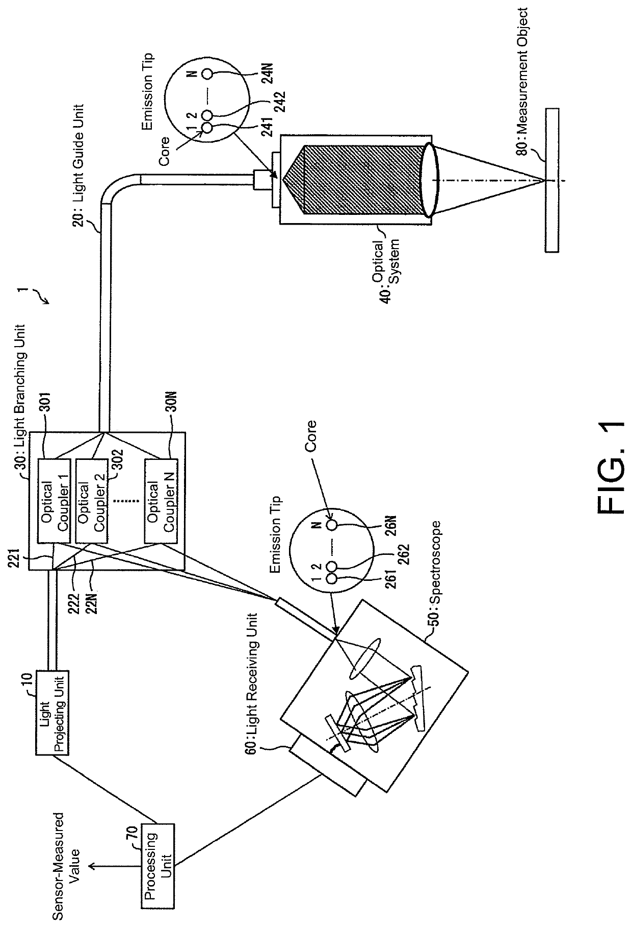
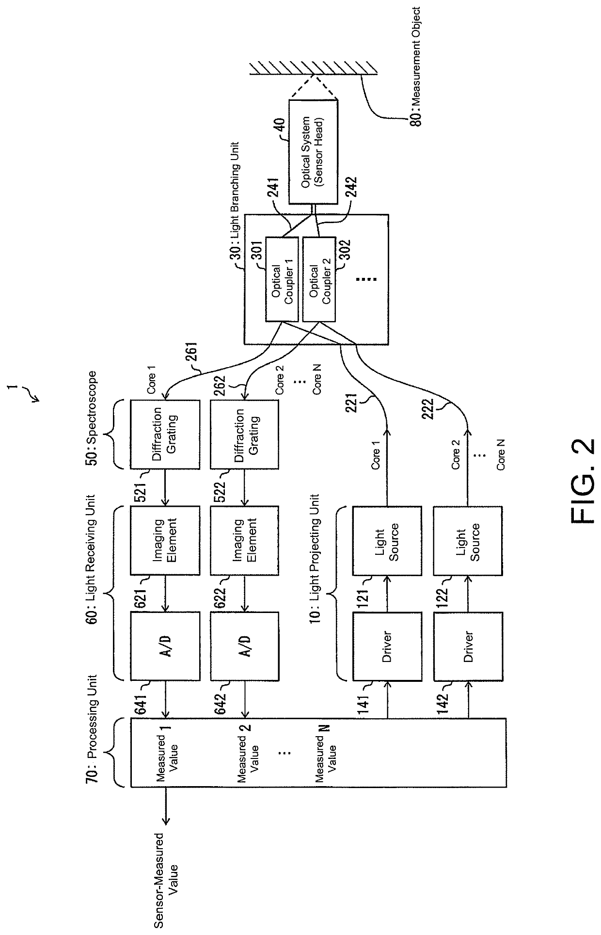
[0036]A configuration of an optical measurement system 1 according to a first embodiment of the invention will be described below with reference to FIGS. 1 and 2. FIG. 1 is a schematic diagram illustrating an example of the optical measurement system 1 according to the first embodiment. FIG. 2 is a schematic diagram illustrating an example of a system configuration of the optical measurement system 1 according to the first embodiment.
[0037]The optical measurement system 1 includes a light projecting unit 10, a light guide unit 20, a light branching unit 30, an optical system 40, a spectroscope 50, a light receiving unit 60, and a processing unit 70.
[0038]The optical measurement system 1 can project a plurality of light beams generated by the light projecting unit 10 to a plurality of positions (hereinafter referred to as spots) on a measuring surface of a meas...
second embodiment
[0072]Another embodiment of the invention will be described below with reference to FIGS. 6 to 8. An optical measurement system 1 according to a second embodiment includes members having the same functions as the members described in the first embodiment and thus description of the members will not be repeated.
[0073]Example of Processing Routine of Processing Unit
[0074]FIG. 6 is a flowchart illustrating an example of a processing routine which is performed by the processing unit 70 of the optical measurement system 1 according to this embodiment.
[0075]Before performing the processing routine illustrated in the flowchart of FIG. 6, the processing unit 70 calculates a distance between each of the pinholes and the measuring surface of the measurement object 80 facing the pinholes based on measured values 1, 2, . . . , N corresponding to the cores 241, 242, . . . , 24N.
[0076]Step S20
[0077]The processing unit 70 compares values indicating the distance for all the cores with a threshold v...
third embodiment
[0095]Another embodiment of the invention will be described below with reference to FIGS. 9A and 9B. FIG. 9A is a schematic diagram illustrating an example of a system configuration of an optical measurement system 1a according to a third embodiment.
[0096]The optical measurement system 1a according to this embodiment includes a single spectroscope 50a and a single light receiving unit 60a. That is, a spectroscope and a light receiving unit are not provided for each of the cores 261, 262, . . . , 26N of the light guide unit 20.
[0097]The optical measurement system 1a according to this embodiment includes members having the same functions as the members described in the first embodiment except for the spectroscope 50a and the light receiving unit 60a and thus description of the members will not be repeated.
[0098]The light receiving unit 60a includes an imaging element 62a and an A / D converter 64a.
[0099]As illustrated in FIG. 9B, the imaging element 62a is a two-dimensional imaging ele...
PUM
| Property | Measurement | Unit |
|---|---|---|
| distance | aaaaa | aaaaa |
| distance | aaaaa | aaaaa |
| distance | aaaaa | aaaaa |
Abstract
Description
Claims
Application Information
 - R&D
- Intellectual Property
- Life Sciences
- Materials
- Tech Scout
- Unparalleled Data Quality
- Higher Quality Content
- 60% Fewer Hallucinations
Browse by: Latest US Patents, China's latest patents, Technical Efficacy Thesaurus, Application Domain, Technology Topic, Popular Technical Reports.
© 2025 PatSnap. All rights reserved.Legal|Privacy policy|Modern Slavery Act Transparency Statement|Sitemap|About US| Contact US: help@patsnap.com


