Image recording apparatus, image recording method, and correction information acquisition method

a technology of image recording and information acquisition, which is applied in the field of image recording apparatus, image recording method, and correction information acquisition method, can solve the problems of density unevenness, difficult to correct density unevenness, unevenness at each connection part of the ejection unit, etc., and achieve the effect of easy acquisition of information required for correction

Active Publication Date: 2020-12-31
DAINIPPON SCREEN MTG CO LTD
View PDF0 Cites 0 Cited by
  • Summary
  • Abstract
  • Description
  • Claims
  • Application Information

AI Technical Summary

Benefits of technology

[0021]By the present invention, it is possible to easily acquire information required for correction.

Problems solved by technology

In the image recording apparatus, in some cases, variation in the amount of ink ejected from a plurality of nozzles or in the spattering direction of droplets is caused due to the processing accuracy of the nozzles, the mounting accuracy of the ejection part, or the like, and as a result, there occurs density unevenness, stripe moire, or the like (hereinafter, referred to simply as “density unevenness”) on the recording medium.
In a so-called “one-pass type” image recording apparatus in which a head part passes over a recording medium only once in image recording, particularly, it is more difficult to correct the density unevenness, as compared with a so-called “multipass type” image recording apparatus in which a head part passes over a recording medium a plurality of times. Further, in a case of using the one-pass type image recording apparatus, since a plurality of ejection units are so provided in the head part as to cross the recording medium, there is a tendency that unevenness occurs at each connection part between the ejection units.
Even if the density unevenness in the record of one color component is corrected, however, there occurs unevenness in an area in which two color components overlap each other in some cases.
As a result, a lot of recording media such as paper, a film, or the like and ink are consumed and environmental load increases, and the operation for obtaining the correction value requires time.
Moreover, in Document 1, since RGB values are conversed into CMYK values after correction values are obtained on an RGB space, it is inevitable that the accuracy is reduced due to an error in the conversion from the three-dimensional space into the four-dimensional space.

Method used


Image

  • Image recording apparatus, image recording method, and correction information acquisition method
  • Image recording apparatus, image recording method, and correction information acquisition method
  • Image recording apparatus, image recording method, and correction information acquisition method

Examples


Embodiment Construction

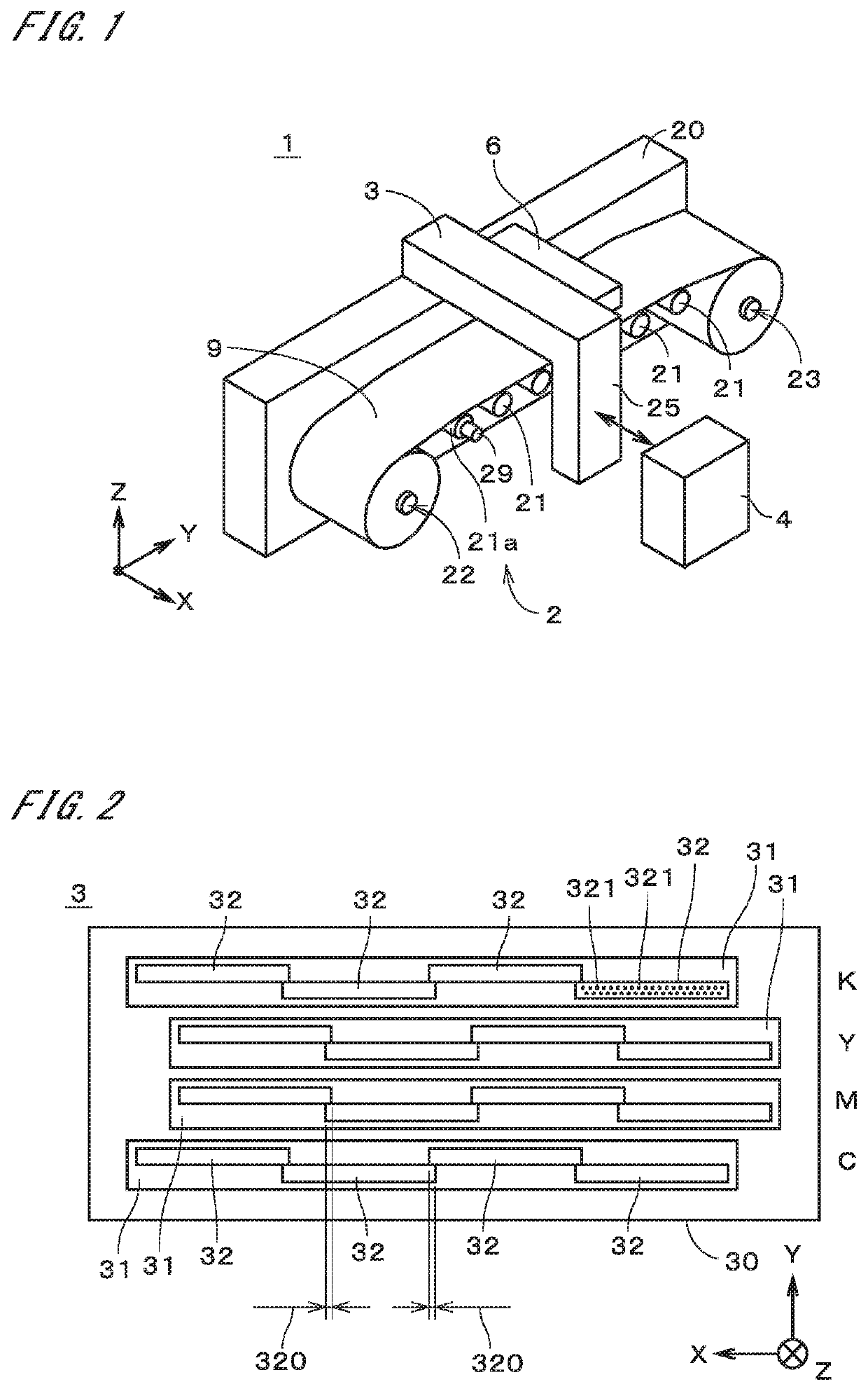
[0033]FIG. 1 is a perspective view showing a configuration of an image recording apparatus 1 in accordance with one preferred embodiment of the present invention. The image recording apparatus 1 is a printer (a so-called ink jet printer) which records a color image on a long sheet-like recording medium 9 by ejecting fine droplets of ink on the recording medium 9. The recording medium 9 is, for example, printing paper.

[0034]In FIG. 1, two horizontal directions perpendicular to each other are represented as an X direction and a Y direction, and a vertical direction perpendicular to the X direction and the Y direction is represented as a Z direction. The X direction and the Y direction in FIG. 1 are not necessarily needed to be in the horizontal direction, and similarly the Z direction is also not necessarily needed to be in the vertical direction. In other words, the upper side and the lower side in FIG. 1 are not necessarily needed to coincide with the upper side and the lower side i...


PUM


Abstract

In an image recording apparatus, when an image is recorded on a recording medium, the recording medium passes through a head part only once. Before the image is recorded, a value of a color component of at least some of pixels included in the image is corrected in order to reduce color mixing unevenness. At that time, on the basis of respective values of two reference color components among a plurality of color components of a correction target pixel, a value of one target color component included among the two reference color components is corrected. Alternatively, on the basis of respective values of three reference color components among the plurality of color components, a value of one target color component or respective values of two target color components included among the three reference color components are corrected.

Description

TECHNICAL FIELD[0001]The present invention relates to a technology for recording an image on a recording medium by ejecting droplets of ink toward a recording medium.BACKGROUND ART[0002]Conventionally, an image recording apparatus which records an image on a recording medium by ink jet method through relative movement of an ejection part which ejects fine droplets of ink from a plurality of ejection ports, with respect to the recording medium, has been used. In the image recording apparatus, in some cases, variation in the amount of ink ejected from a plurality of nozzles or in the spattering direction of droplets is caused due to the processing accuracy of the nozzles, the mounting accuracy of the ejection part, or the like, and as a result, there occurs density unevenness, stripe moire, or the like (hereinafter, referred to simply as “density unevenness”) on the recording medium.[0003]In a so-called “one-pass type” image recording apparatus in which a head part passes over a recor...

Claims


Application Information

Patent Timeline
Patent Type & Authority Applications(United States)
IPC IPC(8): G06K15/02G06K15/10G06K15/00B41J2/21
CPCG06K15/027G06K15/408G06K15/102B41J2/2132G06K15/1878B41J2/01B41J2/155B41J2/21H04N1/6041H04N1/6038
Inventor ICHIOKA, YOSHIKAZU
Owner DAINIPPON SCREEN MTG CO LTD
Why Eureka
Try Eureka