
Solution dispensing system

a technology of dispensing system and solution, which is applied in the direction of dissolving system, instrumentation, phase/state change investigation, etc., can solve the problem of dramatic reduction of the effectiveness of solution

Inactive Publication Date: 2011-08-30
DELAWARE CAPITAL FORMATION INC
View PDF3 Cites 7 Cited by
  • Summary
  • Abstract
  • Description
  • Claims
  • Application Information

AI Technical Summary

Benefits of technology

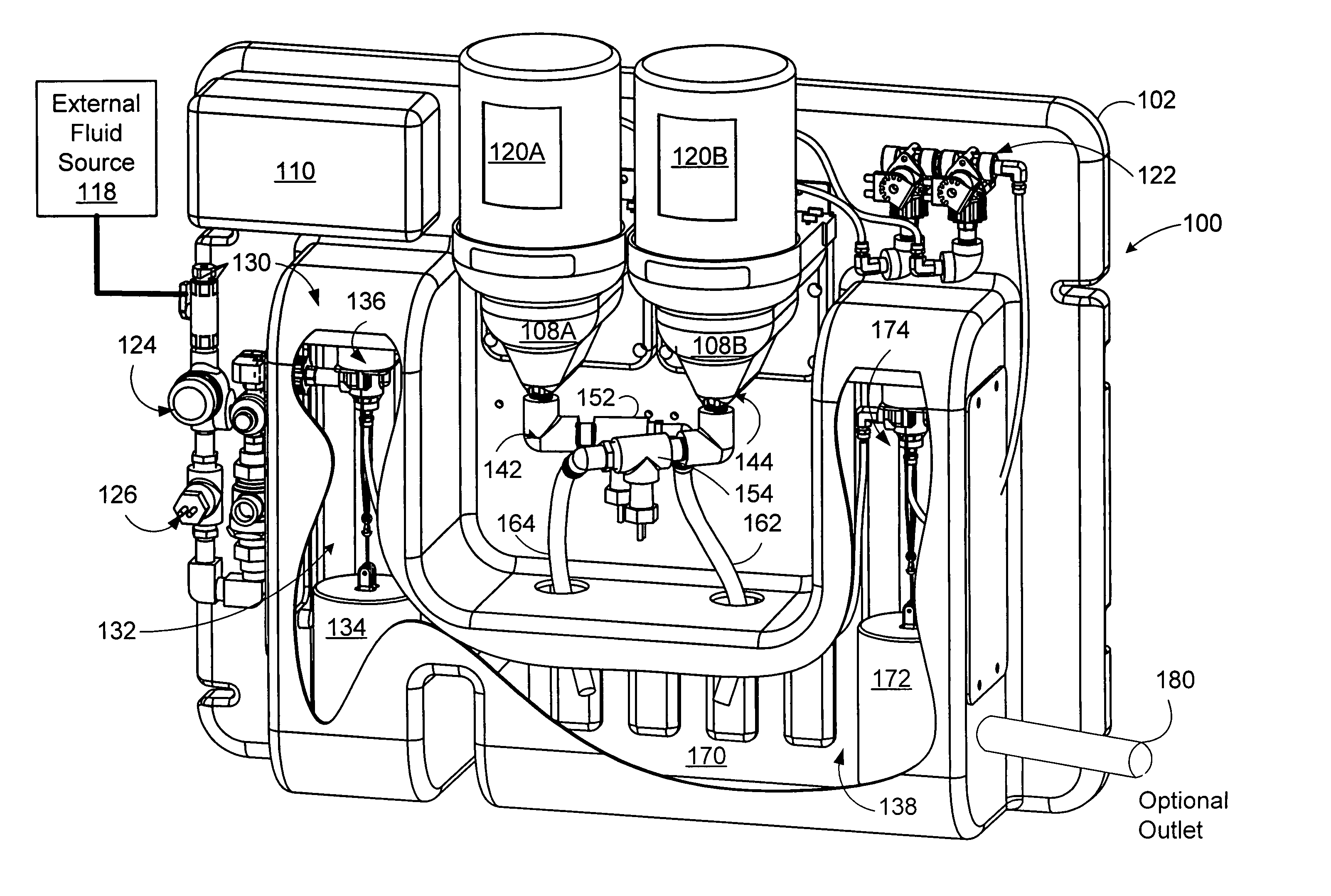
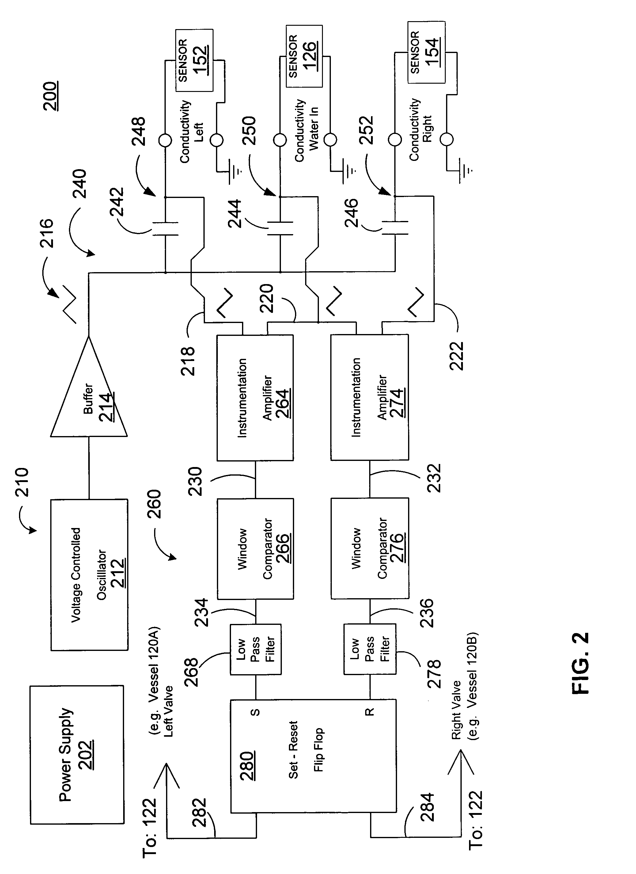
The present invention is a multi-vessel chemical dispensing system that includes at least two vessels for dispensing different chemical solutions. Each vessel has its own sensor to measure a property of the solution before it reaches a fluid receiving region. When the property of the solution reaches a predetermined threshold level, a controller switches the incoming fluid from one vessel to another until a vessel containing sufficient chemicals is found to form a solution. The invention also provides a method for measuring the properties of the solutions and switching between them based on the measurements. The technical effects of the invention include efficient and effective chemical dispensing, improved solution quality, and reduced waste of chemicals.

Problems solved by technology

While, conventional solid chemical dispensing systems have proven effective in providing solutions that reduce the amount of corrosion in boilers, cooling towers, etc., the solution's effectiveness is dramatically reduced when the dissolvable solid chemical is depleted.
Unfortunately, such conventional multi-vessel systems that measure conductivity in the reservoir as a guide, measure the conductivity against a predefined set point value without regard to the change in conductivity in the water used to create the solution.

Method used


Image

  • Solution dispensing system
  • Solution dispensing system
  • Solution dispensing system

Examples


Embodiment Construction

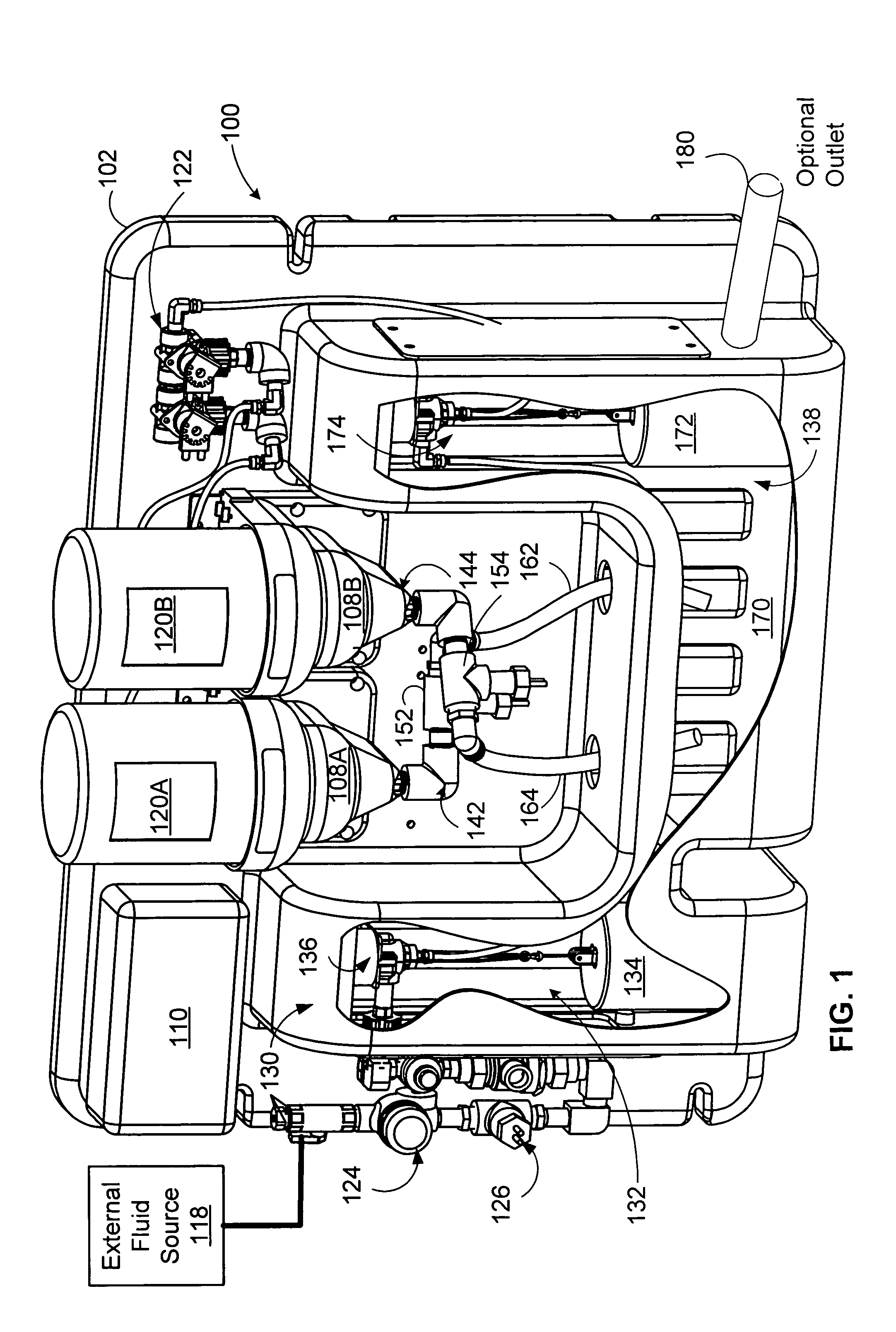
[0020]Embodiments of the invention are directed to a multi-vessel chemical dispensing system. In one embodiment a multi-vessel chemical dispensing system is employed to dispense one or more chemical solutions used by cooling towers, boilers, etc., to protect them from degradation due to oxidation, corrosion, hard water scale, and the like. The solution may be derived by mixing a fluid such as water with a dissolvable chemical compound, or mixture of compounds. To create a solution, the multi-vessel chemical dispensing system includes two or more vessels that contain one or more dissolvable chemical compounds. A fluid is coupled from an external source into one of the vessels selected for dispensing the solution. The solution is generated through agitation of the incoming fluid with the dissolvable chemical compounds in the selected vessel. Each vessel contains an output conduit used to dispense the solution from a selected one of the vessels to a solution receiving region, such as a...


PUM

PropertyMeasurementUnit
DC voltageaaaaaaaaaa
voltageaaaaaaaaaa
voltageaaaaaaaaaa

Abstract

A method and system for switching the dispensing of a first solution from a first vessel to dispensing a second solution from a second vessel when a parameter of the first solution crosses a threshold is described. In one embodiment, a fluid dispensing apparatus includes a first vessel and a second vessel. The first vessel includes an output conduit adapted to dispense the first solution from the first vessel into a fluid receiving region. The second vessel includes an output conduit adapted to dispense the second solution from the second vessel into the fluid receiving region. The apparatus includes a first sensor positioned to measure a parameter of the first solution before the first fluid enters the fluid receiving region. The apparatus also includes a second sensor positioned to measure a parameter of the second solution before the second solution enters the fluid receiving region.

Description

BACKGROUND[0001]The present invention relates in general to solid chemical dispensing systems, and in particular to various embodiments of solid chemical dispensing systems that include multiple vessels used to dispense chemical solutions.[0002]Generally, solid chemical dispensing systems are used to add chemicals to minimize and / or inhibit corrosion in boiler systems, cooling towers, fluid processing systems, etc. Such solid chemical dispensing systems generally employ vessels that contain a dissolvable solid chemical that is mixed with a fluid, such as water, to form a corrosion inhibiting / prevention solution. Typically, the vessels have an output conduit used for dispensing the solution into a holding reservoir, or directly into fluid processing systems.[0003]Conventional solid chemical dispensing systems often use water under pressure that is sprayed into a vessel containing a dissolvable solid chemical. The force of the water, and agitation, mix the chemical with the water insi...

Claims


Application Information

Patent Timeline
Patent Type & Authority Patents(United States)
IPC IPC(8): G01N35/02
CPCB01F1/0022B01F1/0038B01F13/1013B01F15/00207B01F15/00227B01F13/1019Y10T436/115831B01F21/30B01F21/20B01F33/812B01F33/81B01F35/213B01F35/2133
Inventor HOWLAND, DAVID R.HAYAS, MATT
Owner DELAWARE CAPITAL FORMATION INC
Learn More