Disposable expandable cordless lighted retractor

a retractor and expandable technology, applied in the field of surgical instruments, can solve the problems of crowded patient body cavity, poor distribution of light sources, and many drawbacks of systems,

Inactive Publication Date: 2011-09-06
BAYAT ARDESHIR
View PDF17 Cites 80 Cited by
  • Summary
  • Abstract
  • Description
  • Claims
  • Application Information

AI Technical Summary

Problems solved by technology

This further crowds the patient's body cavity and often requires additional operating assistants to manipulate and hold each device.
As ambient light is not always sufficient to light a body cavity, illumination is commonly accomplished by a separate light.
Such systems, however, also have many drawbacks.
For example, the light source often has a limited life and a poor distribution over time.
At the end of its life cycle, the light system's components are typically expensive to replace.
In addition, the bundle is cumbersome since it often drags on the surgeon and impedes the surgeon's movements.
Furthermore, many of the existing devices must be sterilized between uses, a process that may be expensive and time-consuming.
Moreover, procedures to sterilize the device may also damage it.
Even with sterilization procedures, however, there remains a risk of pathogen cross infection because the instrument will be used more than once.
As such, the re-sterilized device will never be as good as new.
In addition, there may be other maintenance and extended warranty issues that are not present with a single-use, disposable device.
As such, they are difficult to hold for long periods of time since their weight induces fatigue in the surgeon's hands and arms.
Moreover, the metal conducts electricity, which can present an additional risk to the patient and surgeon, such as by electrosurgical burns.
However, the light and suction are only at the end of the device; so light and suction are limited to the end of the device and do not affect the entire breast pocket.

Method used


Image

  • Disposable expandable cordless lighted retractor
  • Disposable expandable cordless lighted retractor
  • Disposable expandable cordless lighted retractor

Examples


Embodiment Construction

[0027]The detailed description set forth below in connection with the appended drawings is intended as a description of presently-preferred embodiments of the invention and is not intended to represent the only forms in which the present invention may be constructed or utilized. The description sets forth the functions and the sequence of steps for constructing and operating the invention in connection with the illustrated embodiments. However, it is to be understood that the same or equivalent functions and sequences may be accomplished by different embodiments that are also intended to be encompassed within the spirit and scope of the invention.

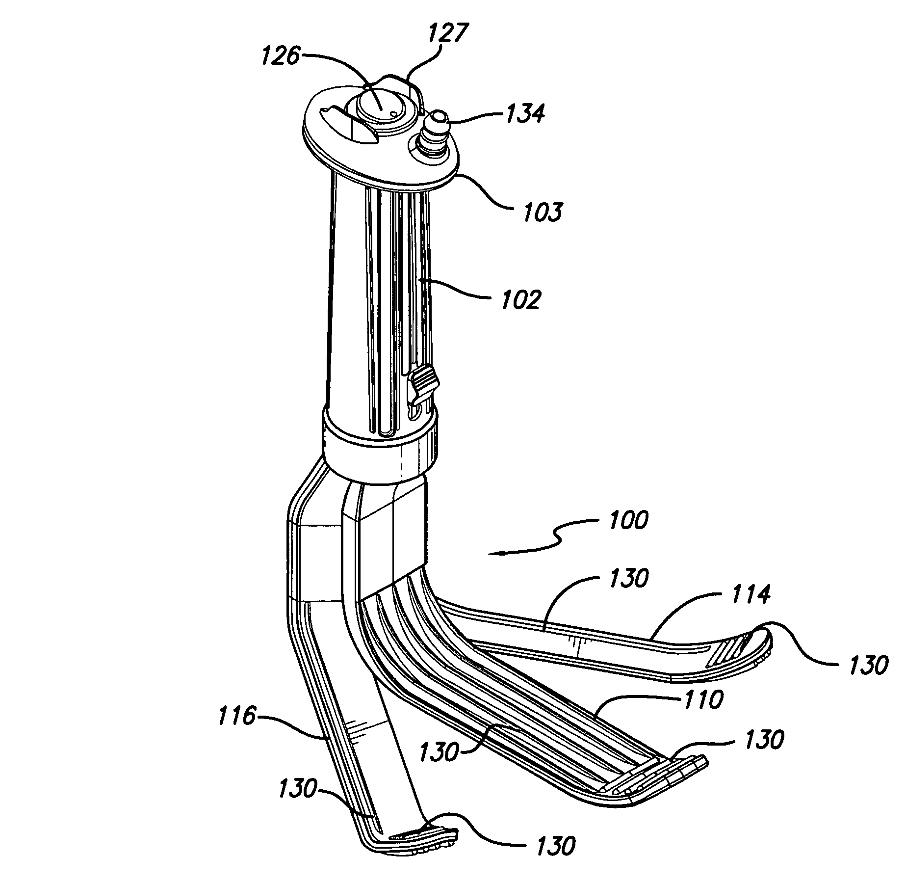
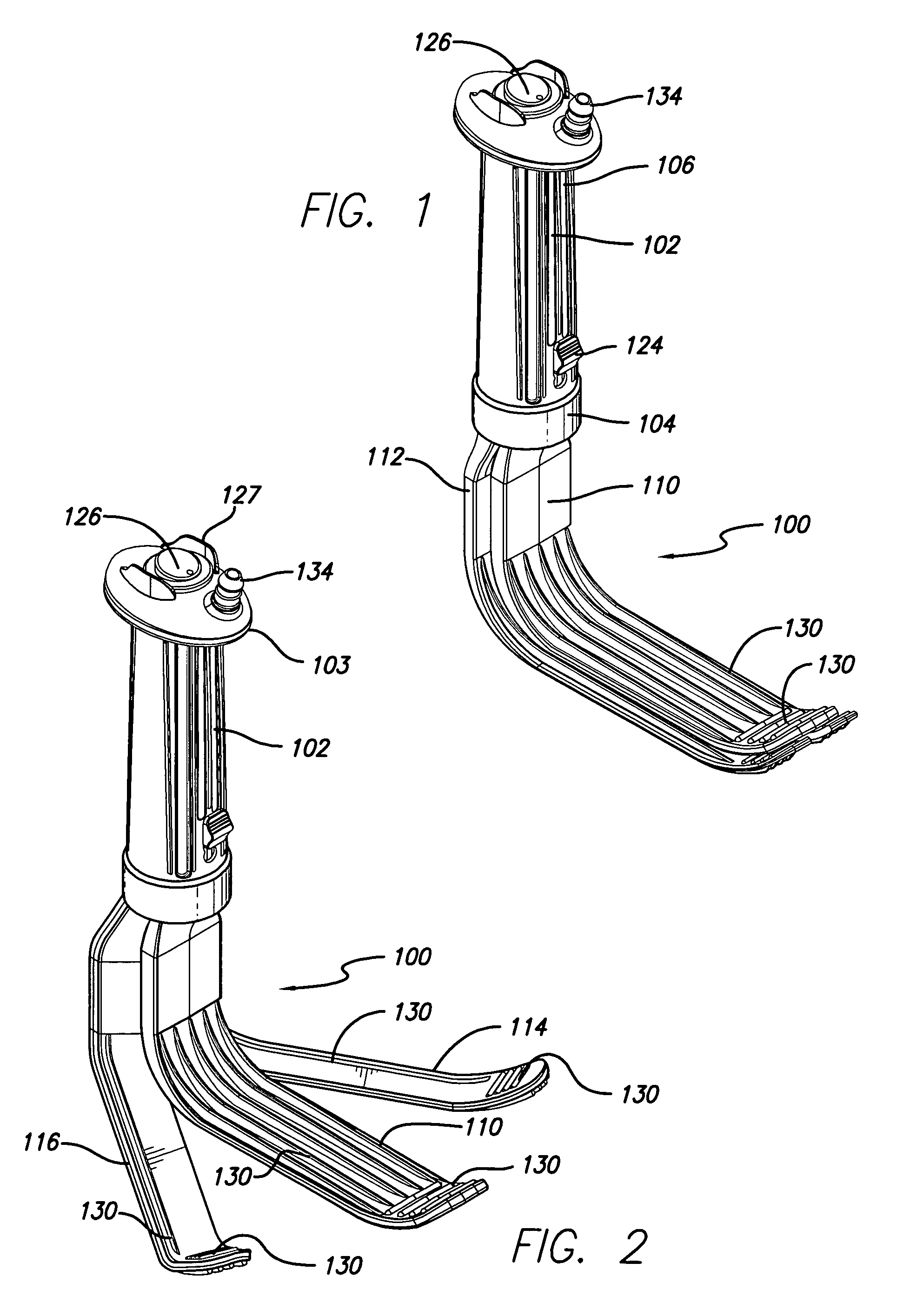
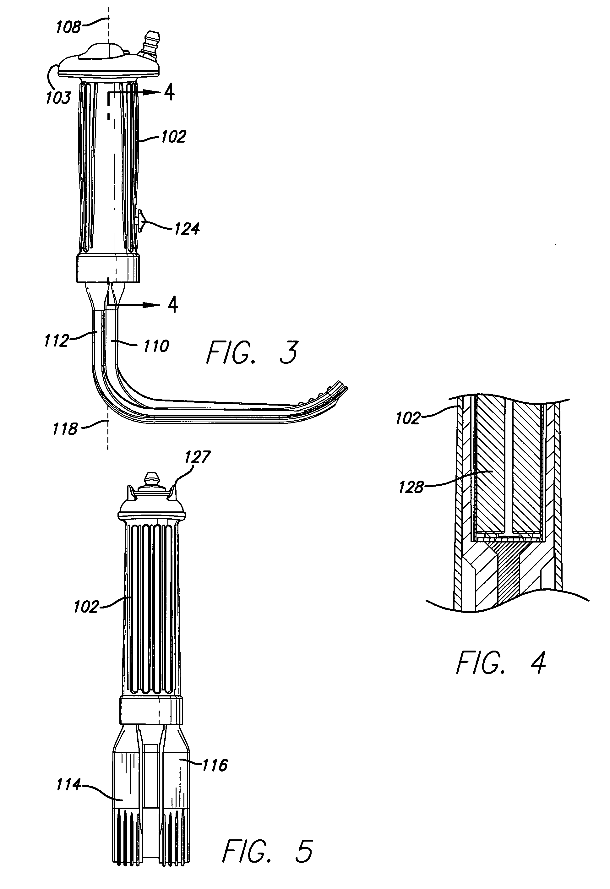
[0028]Referring to the accompanying figures, a surgical instrument 100 allows a user to manipulate and illuminate a patient's tissues 122. The manipulation, for example, may be expansion or retraction of the patient's skin, muscle, or bone. Expansion and retraction may also be performed simultaneously. Depending on the embodiment utilized, ...


PUM


Abstract

A hand-held, surgical instrument to manipulate a patient's tissues having a grip, a first blade, a second blade, a blade actuator, at least one blade rib, a light, and a power source. The first blade and the second blade each extend from the base end of the grip. The second blade is divided longitudinally into a left segment and a right segment, which are each pivotable about a common axis. Movement of the blade actuator causes the segments of the second blade to pivot about the common axis. The light illuminates the patient's tissues proximate the blades. The device may include suction ports on the underside of the first blade to provide aspiration. The blade rib may include multiple longitudinal blade ribs extending along the length of the first blade, the second blade, or both. The blade rib may also include multiple transverse blade ribs extending along the width of the first blade, the second blade, or both. The device may also include an integral camera and wireless transmitter to provide images of the patient's tissues to a separate display.

Description

CROSS-REFERENCES TO RELATED APPLICATIONS[0001]This patent application is a continuation-in-part and claims the benefit of U.S. patent application Ser. No. 11 / 439,316 filed May 22, 2006 now U.S. Pat. No. 7,384,392 for Disposable Expandable Cordless Lighted Retractor, which application is incorporated by this reference.TECHNICAL FIELD[0002]This invention relates to surgical instruments used to manipulate a patient's tissues, such as skin, bone, and muscle.BACKGROUND ART[0003]Surgical retractors and expanders are used to manipulate a patient's tissues, such as skin, muscle, or bone, and are commonly utilized by surgeons and dentists on the human body and by veterinarians on animals. Retractors have blades that tend to pull the tissue to create more room for a surgeon to view an area of interest, such as a body cavity, and to manipulate other surgical tools. Expanders perform a similar function by tending to push the tissue instead of pulling it. Retractors and expanders are available i...

Claims


Application Information

Patent Timeline
Patent Type & Authority Patents(United States)
IPC IPC(8): A61B1/32
CPCA61B17/02A61B2017/00734A61B2019/5208A61B1/3132A61B1/32A61B2090/308
Inventor BAYAT, ARDESHIR
Owner BAYAT ARDESHIR
Why Eureka
Try Eureka