Method for fabricating drive belt

a technology of drive belts and belt covers, which is applied in the direction of belts, mechanical equipment, other domestic objects, etc., can solve the problems of belt top fabric wear, belt joint breakage, and flat pulley wear

Inactive Publication Date: 2011-09-06
BANDO CHEM IND LTD
View PDF10 Cites 1 Cited by
  • Summary
  • Abstract
  • Description
  • Claims
  • Application Information

AI Technical Summary

Problems solved by technology

Meanwhile, in belt drive systems in which a drive belt is wrapped, with its back face inside, around a resin-made flat pulley, a problem arises that the flat pulley is worn out by the top fabric of the belt.
However, when the cylindrical rubber is formed to cause no sag from the cylindrical mold, it receives a circumferential tension, which may break the joining at the rubber juncture.

Method used


Image

  • Method for fabricating drive belt
  • Method for fabricating drive belt
  • Method for fabricating drive belt

Examples


Embodiment Construction

[0018]An embodiment of the present invention will be described below in detail with reference to the drawings.

[0019](V-Ribbed Belt B)

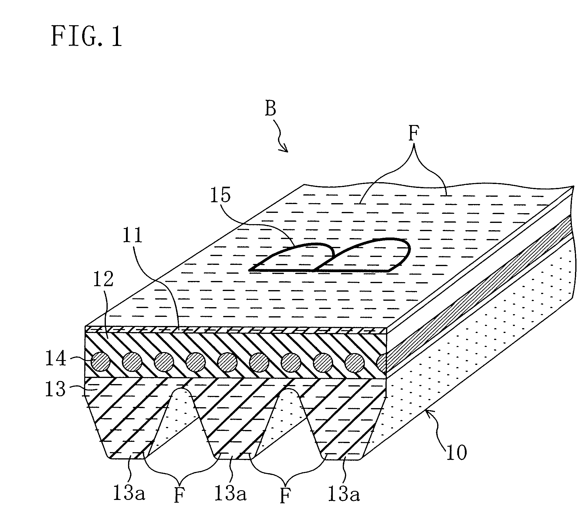
[0020]FIG. 1 shows a V-ribbed belt B according to this embodiment. The V-ribbed belt B is used, for example, to transmit power from a motor vehicle engine to engine accessories to drive them and formed with a length of 1000 to 2500 mm, a width of 10 to 20 mm and a thickness of 4.0 to 5.0 mm.

[0021]The V-ribbed belt B includes a V-ribbed belt body 10 formed in a triple layered structure including a backing rubber layer 11 forming an outer part, an adhesion rubber layer 12 forming an intermediate part and a ribbed rubber layer 13 forming an inner part. The adhesion rubber layer 12 has a cord 14 embedded therein in a spiral with a certain pitch in the belt width direction.

[0022]The backing rubber layer 11 is formed in the shape of a small-thickness strip of long rectangular cross section and has a thickness of 0.30 to 2.00 mm, for example.

[0023]The backing...


PUM

PropertyMeasurementUnit
thicknessaaaaaaaaaa
widthaaaaaaaaaa
lengthaaaaaaaaaa

Abstract

A method for fabricating a drive belt includes: a cylindrical rubber formation step of forming a cylindrical rubber by roundly joining an uncrosslinked rubber sheet (31); and a mold covering step of covering a cylindrical mold with the cylindrical rubber formed in the cylindrical rubber formation step. A mark hot-transfer sheet (35) is adhered by hot pressing to the juncture of the cylindrical rubber to cover the juncture on the inside of the cylindrical rubber.

Description

TECHNICAL FIELD[0001]This invention relates to a method for fabricating a drive belt.BACKGROUND ART[0002]In fabricating a friction drive belt exposing its rubber part, normally, component materials of the belt are set on the outer periphery of a cylindrical mold in order from a component material for an outermost belt component. Specifically, the belt component materials are set on the outer periphery of the cylindrical mold by laying them one on another in order of a woven fabric constituting a top fabric, an uncrosslinked adhesion rubber, a twisted yarn constituting a cord, another uncrosslinked adhesion rubber and an uncrosslinked compression rubber. Known as a method for setting an uncrosslinked rubber on the cylindrical mold in such a case is a method of forming an uncrosslinked rubber into a cylindrical rubber and fitting it onto the cylindrical mold.[0003]For example, Patent Document 1 discloses a drive belt fabrication method including: a fabric setting step of fitting a cyl...

Claims


Application Information

Patent Timeline
Patent Type & Authority Patents(United States)
IPC IPC(8): B29D29/00
CPCB29D29/10F16G1/10F16G1/28F16G5/20B29C65/08B29C65/4835B29C65/5042B29C65/72B29C66/1142B29C66/435B29C66/7375B29K2021/00B29K2105/101B29K2105/246B29K2267/00B29K2277/10B29L2031/7094B29C65/18B29C65/4825B29C65/4815B29C65/5092B29C65/5021B29C65/5007B29C65/00
Inventor TAKAHASHI, SHINJINAYA, MASAHIDEHAYASHI, TAKEHIROSANEMATSU, KENTAROU
Owner BANDO CHEM IND LTD
Why Eureka
Try Eureka